DR Power 9 HP (March 2004 - March 2010) User Manual
Page 13
SECTION VI – CUTTER HEAD
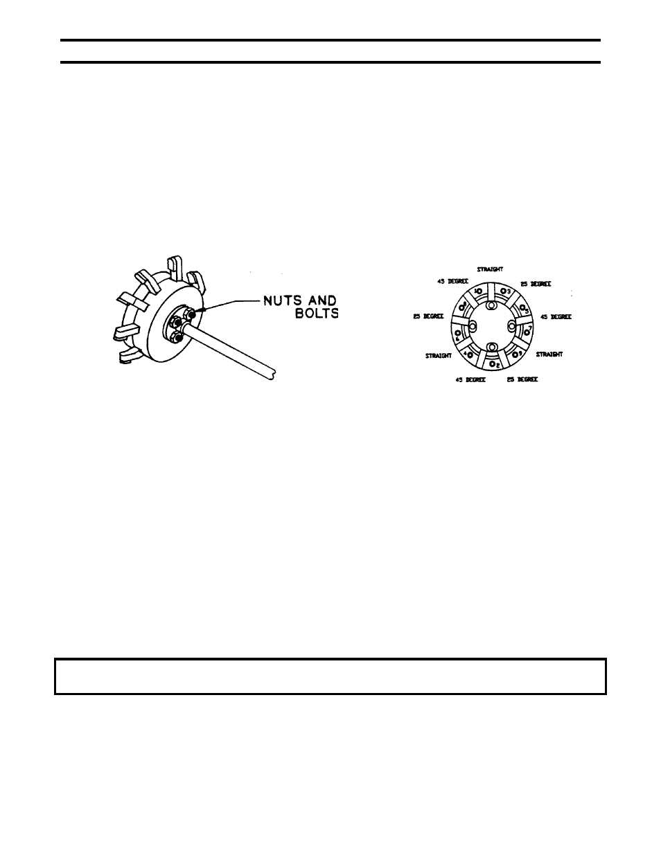
The cutter head is fastened to the mounting flange on the spindle with four 3/8-16 x 1-3/4” bolts. Be sure to
check them frequently for tightness. (Figure 12)
TEETH
Your stump cutter is equipped with carbide tipped teeth. (Items 24d, 24e, 24f, pg. 15) Carbide retains its
sharpness longer, cuts faster and smoother and can withstand heat, but they will wear. Sharpen the teeth
before excessive wear or when they look dull or rounded. Check the teeth on the cutter head after each use.
Always check the 45-degree tooth first because it is the most abused being a “digger and leader”. Any cutter
tooth with less than a 10-degree relief (see fig. 15, pg. 14) will cause poor performance, smoke and burn marks.
By keeping the teeth sharp, you will prevent frustration at the job site. It only takes a few minutes to touch them
up before you go out on a job. If the unit receives heavy use, a second cutter head assembly can be purchased
as a back up while the other head is being sharpened.
fig. 12
fig. 13
FOR PROPER OPERATION:
1. Teeth should be installed according to the pattern shown in Figure 13 above.
2. Cutter head must never be run with a missing or damaged tooth.
CAUTION: Excessive vibration is usually a result of broken or missing teeth. Stop engine, disconnect spark
plug wire and inspect.
TO SHARPEN
Teeth can be removed and sharpened individually or while still attached to the cutter head.
1. Remove entire cutter head (see figure 12) by removing the four 3/8”-16 nuts and bolts.
2. To remove the teeth from the cutter head, remove the 9 cap screws using the 5/16” Allen wrench
provided.
3. Tap any of the 9 teeth with a soft hammer to “pop” the cover off the cutter body.
4. Remove the 9 teeth from their slots.
WARNING: WHEN SHARPENING TEETH, ALWAYS WEAR EYE PROTECTORS AND A
DUST MASK OR RESPIRATOR. CARBIDE DUST CAN BE DANGEROUS IF INHALED.
13