DR Power 9 HP (March 2004 - March 2010) User Manual
Page 14
5. Any bench-type or pedestal style grinder with a “Green wheel” (silicon carbide grinding wheel or
diamond wheel) may be used on the carbide teeth. A regular gray wheel (coarse grinding wheel) is
needed for grinding the steel relief. It is best if you can set up the grinder with a coarse wheel on one
side and “Green Wheel” on the other side.
6. Teeth may be ground free hand since precision is not important. Any variance between teeth will not be
noticed.
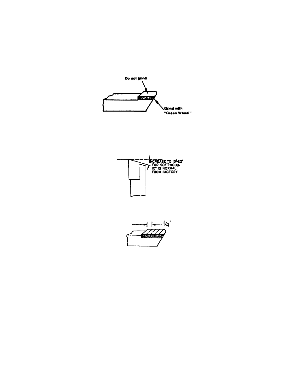
7. Using the “Green Wheel”, grind the end of the carbide until the edge is sharp. Avoid grinding on the
face of the carbide, which would reduce its thickness and weaken it, making it more susceptible to
cracking and chipping. (Figure 14)
fig. 14
8. As the end of the carbide is ground away, you will have to grind “relief” on the square steel shank. The
steel must be ground with the regular coarse grinding wheel and not the “Green Wheel”.
9. Although the angle is not critical, always grind the tooth so that there is enough “relief” under the
carbide edge (minimum 10 degrees). (Figure 15)
fig. 15
10. The tooth may continue to be ground until the carbide has approximately 1/4” remaining (Figure 16).
fig. 16
11. Before reinstalling the teeth, wire brush the inside of the cutter body and the cap screws. Spray with
light oil or WD40 and reassemble. Remember to reassemble teeth in the same order: 45 degree offset,
25 degree offset, and straight; repeated three times (Figure 13, pg. 13). Make sure to align the notch in
the teeth with the slot in the cutter head body so the cover plate can be assembled properly.
12. Torque cap screws on cover plate (item #24c, pg. 15) to 25 ft. lb. the first time around to insure even
pressure on the teeth. Alternate tightening screws in a crisscross pattern. Final tighten to 45 ft. lb.
13. The teeth can also be sharpened without removing them from the cutter head. Sharpen them free hand
by holding the entire head up to the grinding wheels.
14. To reassemble cutter head to drive shaft weldment:
15. Clean mating surfaces of cutter head and shaft. Spray both with light oil or WD40.
16. Reinstall cutter head using new 3/8” split lock washer and nuts
17. Pre-tighten nuts in crisscross pattern to 25 ft. lb. Final tighten to 45 ft. lb.
CAUTION: CHECK FOR LOOSE PARTS BEFORE USING YOUR STUMP GRINDER.
14