Front displays – FiberPlex FOM-1090 User Manual
Page 10
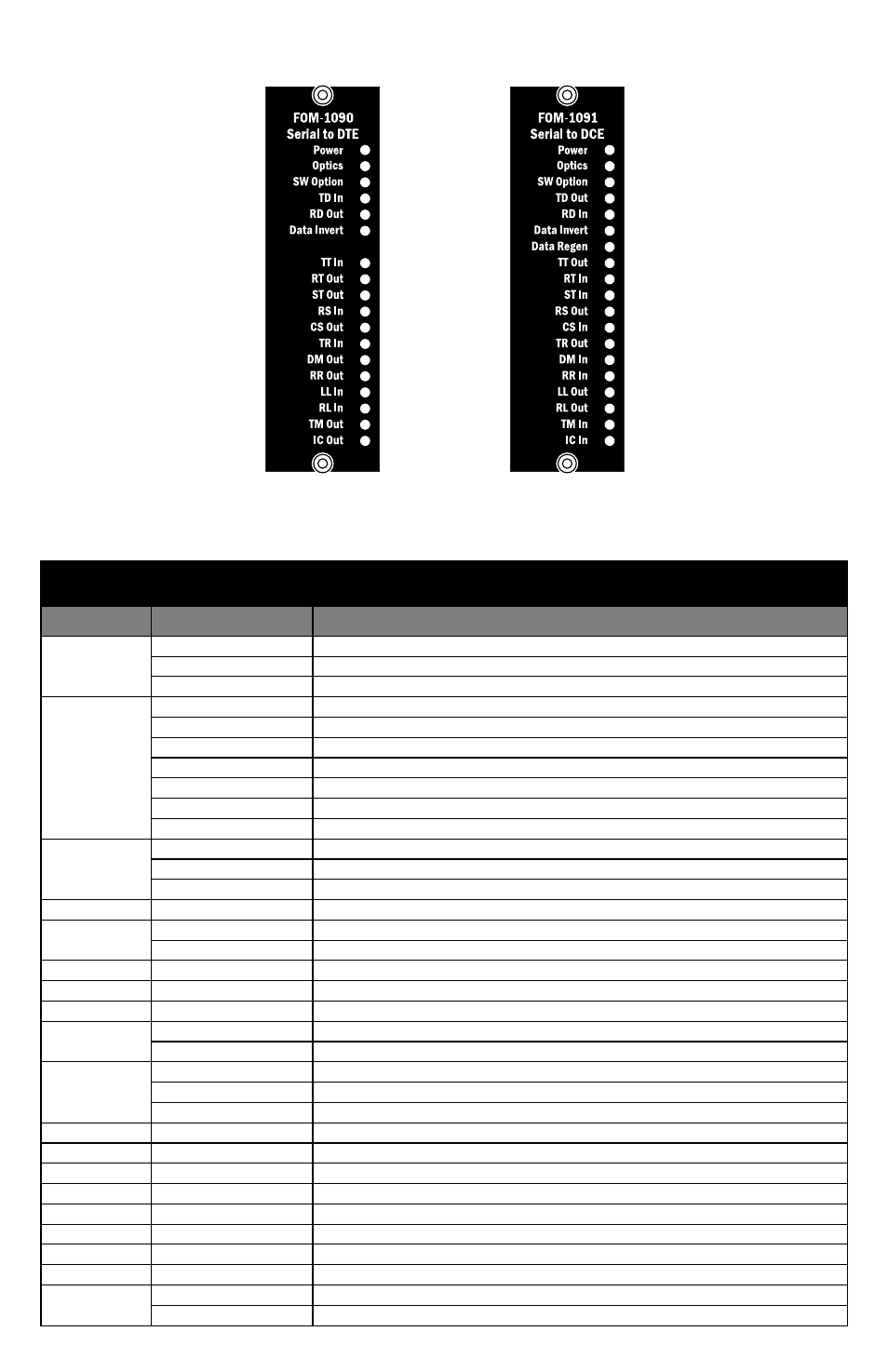
Front Displays
Figure 2 FOM‐1090 (left) and FOM‐1091 (right) Displays
These LEDs indicates status as per the following table
Display
LEDs
Label
Status
Description
Power
Steady Green
Card power supply normal operation
Steady Red
Card power supply failure or in over‐current protection
Off
Card failure or main power failure
Optics
Steady Green
Optics in sync at each end of link
Flashing Green
Local optical RX is receiving errors
Steady Yellow
Remote optical RX loss of signal or sync
Flashing Yellow
Local optical RX signal present, but no sync
Flashing Orange
Card type mismatch at remote end; the two cards are not compatible
Steady Red
No optical RX signal
Off
Card failure
SW Option
Steady Green
Optional switch setting is in use
Flashing Red
Card is in Loop Back mode
Off
No optional switch setting is in use; text is turned off
TD
Flashing
Data transitions detected
RD
Steady
Data in steady SPACE condition
Off
Data in steady MARK condition
TT
Flashing
Clock transitions detected
RT
Steady
Clock in steady On state
ST
Off
Clock in steady Off state
Data Invert
Steady Green
Optional data invert in use – typically used for MIL interfaces
Off
No optional data invert – normal operation; text is turned off
Data Regen
Steady Green
Optional TD signal regeneration in use – FOM‐1091 only
Flashing Red
Optional TD regeneration configuration error
Off
No TD regeneration – normal operation; text is turned off
RS
Steady
Control signal in On state
CS
Off
Control signal in Off state
TR
Yellow/Orange/Red
Yellow for a DCE unit, Orange for a DTE; solid Red is a disabled interface
DM
Yellow/Orange/Red
Yellow for a DCE unit, Orange for a DTE; solid Red is a disabled interface
RR
Yellow/Orange/Red
Yellow for a DCE unit, Orange for a DTE; solid Red is a disabled interface
LL
Yellow/Orange/Red
Yellow for a DCE unit, Orange for a DTE; solid Red is a disabled interface
RL
Yellow/Orange/Red
Yellow for a DCE unit, Orange for a DTE; solid Red is a disabled interface
TM
Yellow/Orange/Red
Yellow for a DCE unit, Orange for a DTE; solid Red is a disabled interface
IC
Steady
Control signal in On state
Off
Control signal in Off state