Sfp msa compliance – FiberPlex FOM-1090 User Manual
Page 9
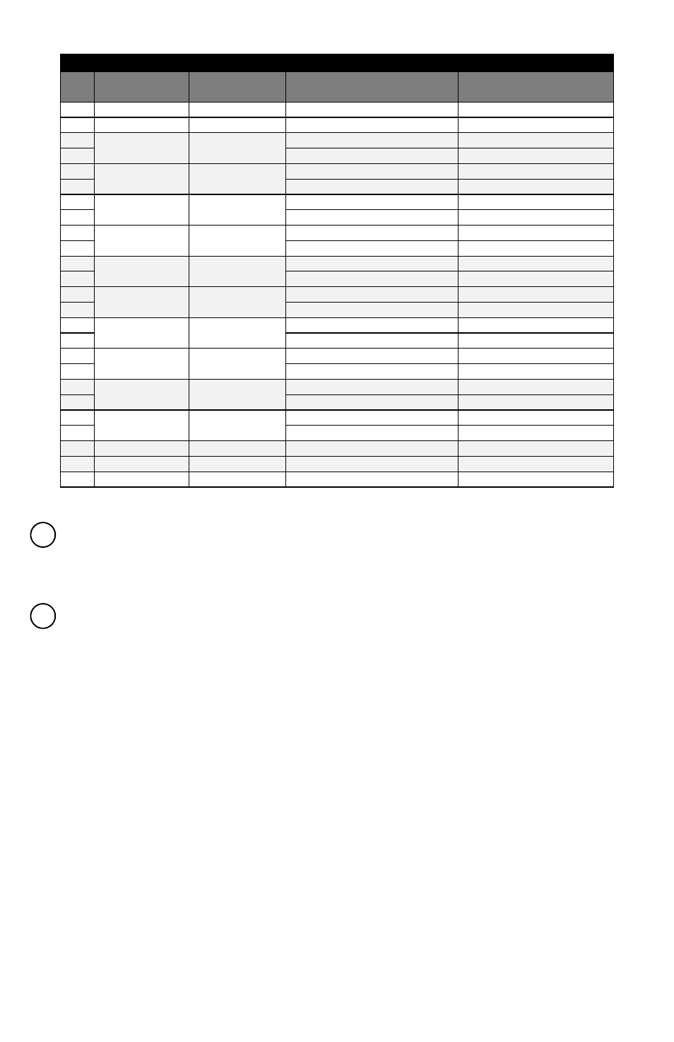
Pinouts (V.35 with adapter cable information)
Pin
FOM‐1091
(DCE) Direction
FOM‐1090
(DTE) Direction
V.35
M‐34 Pin
1
Chassis Ground
A
7
Signal Ground
B
2
Out
In
TD A (V.35)
P
14
TD B (V.35)
S
3
In
Out
RD A (V.35)
R
16
RD B (V.35)
T
4
Out
‐
In
‐
RTS/RS (V.28)
C
19
‐
‐
5
In
‐
Out
‐
CTS/CS (V.28)
D
13
‐
‐
20
Out
‐
In
‐
DTR/TR (V.28)
H
23
‐
‐
6
In
In
Out
Out
DSR/DM (V.28)
E
22
RI/IC (V.28)
J
24
Out
In
TT A (V.35)
U
11
TT B (V.35)
W
8
In
‐
Out
‐
DCD/RR (V.28)
F
10
‐
‐
15
In
Out
ST A (V.35)
Y
12
ST B (V.35)
AA
17
In
Out
RT A (V.28)
V
9
RT B (V.28)
X
18
Out
In
LL (V.28)
L
25
In
Out
TM (V.28)
NN
21
Out
In
RL (V.28)
N
Interface Status LED – This LED will flash a fixed number of times indicating the selected interface mode.
It will be yellow for a DCE unit and orange for a DTE. It will be solid red for a disabled interface (See section
“DIP Switch Settings”, subsection “Configuring DIP Switch Parameters” for more information).
Optical Fiber Connections – This position may be a pair of ST connectors, LC connectors or an SFP slot, if
so ordered.
SFP MSA Compliance
The SFP Multisource Agreement (MSA) is an agreement that was drafted among competing manufacturers of
SFP optical modules. The SFF Committee was formed to oversee the creation and maintenance of these
agreements including the SFP MSA designated as INF‐8074i. This agreement describes a mutually agreed upon
standard for the form and function of SFP modules. However, not all SFPs produced are MSA compliant. The
MSA provides for a transceiver (TX/RX) pinout. Other industries such as broadcast had the need for dual TX
and dual RX SFP for uni‐directional applications such as video. Naturally, a non‐MSA standard was introduced
allocating pinout assignments for dual output and dual input I/O configurations. In addition, the some of the
internal serial communication pins were reassigned.
The FOM‐1090/1091 will only accept MSA compliant SFP Modules.
6
7