FiberPlex FOM-1090 User Manual
Page 6
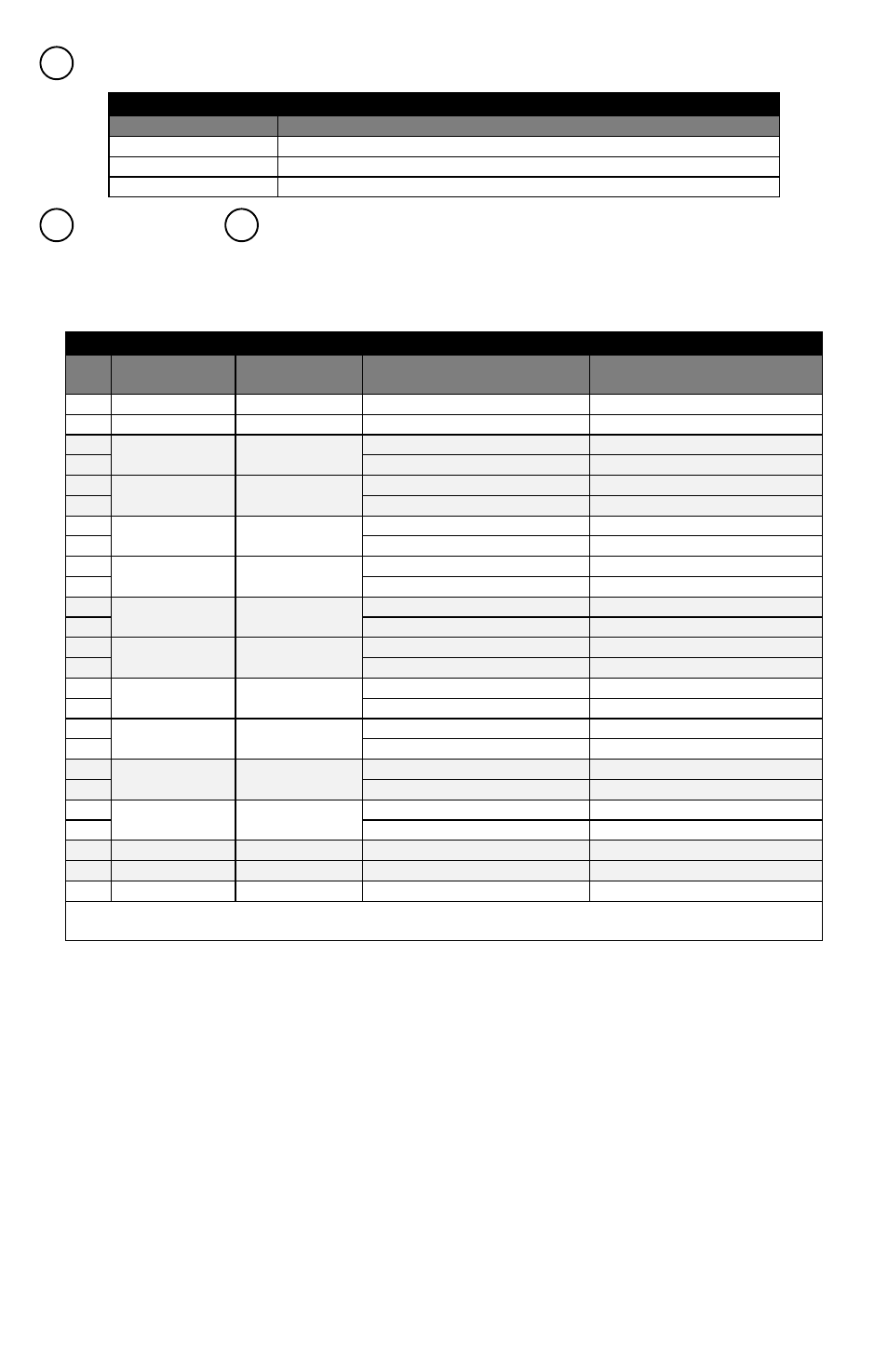
Status LED – This LED, for each position, indicates status as per the following table;
DTE Connector &
DCE Connector – Connect Data Terminal Equipment and Data Communications
Equipment at these ports. The DTE is a female (sockets), D‐subminiature, 25‐position connector; the DCE is
similar, but male (pins). Jackscrews are provided for securement. See pinout below.
Pinouts (TIA‐530, TIA‐530A [422])
Pin
FOM‐1091
(DCE) Direction
FOM‐1090
(DTE) Direction
TIA‐530 Configuration
TIA‐530A Configuration
1
Chassis Ground
Chassis Ground
7
Signal Ground
Signal Ground
2
Out
In
Send Data A (SD) (V.11)
Send Data A (SD) (V.11)
14
Send Data B (SD\) (V.11)
Send Data B (SD\) (V.11)
3
In
Out
Receive Data A (RD) (V.11)
Receive Data A (RD) (V.11)
16
Receive Data B (RD\) (V.11)
Receive Data B (RD\) (V.11)
4
Out
In
Request To Send A (RTS) (V.11)
Request To Send A (RTS) (V.11)
19
Request To Send B (RTS\) (V.11)
Request To Send B (RTS\) (V.11)
5
In
Out
Clear To Send A (CTS) (V.11)
Clear To Send A (CTS) (V.11)
13
Clear To Send B (CTS\) (V.11)
Clear To Send B (CTS\) (V.11)
20
Out
In
Terminal Ready A (TR) (V.11)
Terminal Ready (TR) (V.10)
23
Terminal Ready B (TR\) (V.11)
‐
6
In
Out
Data Set Ready A (DSR) (V.11)
Data Set Ready (DSR) (V.10)
22
Data Set Ready B (DSR\) (V.11)
Incoming Call (IC) (V.10)
24
Out
In
Terminal Timing A (TT) (V.11)
Terminal Timing A (TT) (V.11)
11
Terminal Timing B (TT\) (V.11)
Terminal Timing B (TT\) (V.11)
8
In
Out
Receiver Ready A (RR) (V.11)
Receiver Ready A (RR) (V.11)
10
Receiver Ready B (RR\) (V.11)
Receiver Ready B (RR\) (V.11)
15
In
Out
Send Timing A (ST) (V.11)
Send Timing A (ST) (V.11)
12
Send Timing B (ST\) (V.11)
Send Timing B (ST\) (V.11)
17
In
Out
Receive Timing A (RT) (V.11)
Receive Timing A (RT) (V.11)
9
Receive Timing B (RT\) (V.11)
Receive Timing B (RT\) (V.11)
18
Out
In
Local Loopback (LL) (V.10)
Local Loopback (LL) (V.10)
25
In
Out
Test Mode (TM) (V.10)
Test Mode (TM) (V.10)
21
Out
In
Remote Loopback (RL) (V.10)
Remote Loopback (RL) (V.10)
Note: On the TIA‐530A interface the DM and TR signals become single‐ended and the single‐ended signal IC is
added.
Power Status LED
Status
Description
Steady Green
Card power supply normal operation
Steady Red
Card power supply failure or in over‐current protection
Off
Card failure or main power failure
3
4
5