Flowserve M Slurry User Manual
Page 23
M SLURRY USER INSTRUCTION ENGLISH 71569241 - 02/08
Page 23 of 60
®
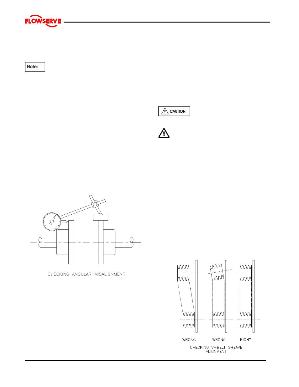
Mount the magnetic base on the pump half coupling
hub, either the face or O.D. as shown in the sketch.
Place the dial indicator button on the outside diameter
of the driver half coupling hub.
The length of extension rods should be kept at
a minimum to reduce deflection.
Rotate the pump shaft and record the dial reading at the
top, bottom and each side. Correct the parallel
alignment by adding or removing shims under the driver
and/or moving the driver horizontally. Repeat this
procedure until the maximum total indicator reading
(T.I.R.) is within 0.076 mm (0.003 inch.)
Angular Alignment:
Mount the magnetic base on the pump half coupling
hub, either the face or O.D. as shown in the sketch.
Move the dial indicator button to indicate on the face of
the driver half coupling hub as close to the outside
diameter as possible. When convenient the indicator
can be placed on the inside face to keep spans short.
Turn both shafts 360
° and record the dial readings at
90
° intervals. Adjust the shims under the motor as
required and repeat the procedure until the angular
alignment is within 0.0005 mm (T.I.R.) per mm (0.0005
inch per inch) of maximum hub diameter.
Repeat the checks on parallel and angular alignment,
ensuring the mounting bolts are secure, until the unit is
properly aligned. Note that correction in one direction
may affect the alignment in another direction. Re-check
the gap between the coupling hubs.
If any difficulty is encountered in achieving the
recommended alignment tolerances, the runout of the
pump and driver shafts and each coupling hub diameter
and face should be checked. Occasionally, due to
practical and unavoidable manufacturing tolerance
build-up associate with the pump, coupling and driver, it
may be necessary to match up the two coupling hubs in
the most advantageous relative angular position in order
to achieve an acceptable alignment.
Do not install the coupling spacer or sleeve until
grouting is complete and cured and the alignment is re-
checked.
When the electric motor has sleeve bearings it is
necessary to ensure that the motor is aligned to run
on its magnetic centreline. A button (screwed into
one of the shaft ends) is normally fitted between the
motor and pump shaft ends to fix the axial position.
If the motor does not run in its
magnetic centre the resultant additional axial force
may overload the pump thrust bearing.
Complete piping as below and see sections
4.7, Final shaft alignment check up to and including
section 5, Commissioning, startup, operation and
shutdown
before connecting driver and checking
actual rotation.
4.5.2.2 V-Belt Drive Units:
Check that both sheaves are free of grease, rust, nicks
or burrs. Install the correct size sheave on the pump
shaft and locate the sheave axially to minimize
overhang. Re-check the impeller axial clearance and
ensure that the pump is properly secured to the
baseplate. Install the driver on the adjustable base
provided and install the driver sheave in line with the
pump sheave. Ensure that the sheaves are tight on the
shafts. With a dial indicator, check the runout on the
periphery and face of each sheave to ensure that each
is running true. Tighten the adjustable base and check
that the driver rotation in the correct direction and that
vibration levels are not unacceptable.