Flowserve M Slurry User Manual
Page 29
M SLURRY USER INSTRUCTION ENGLISH 71569241 - 02/08
Page 29 of 60
®
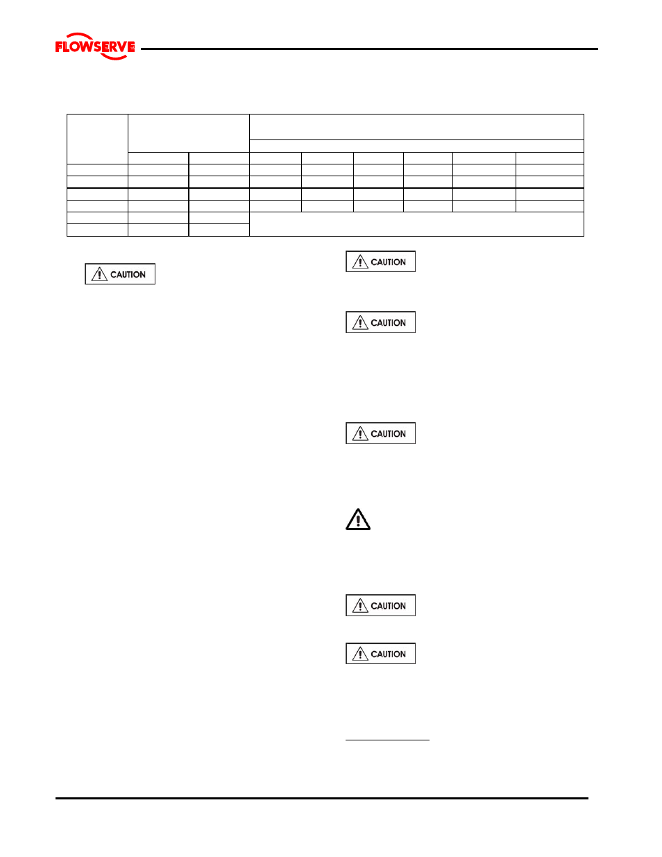
5.2.3 Recommended fill quantities
TABLE 5.2.3 OIL AND GREASE QUANTIES
BEARING
OIL SUMP
CAPACITY
INITIAL GREASE CAPACITIES
FRAME
THRUST BEARING
LINE BEARING
SIZE NO.
U.S. GAL.
LITRES
OZ.
CU. IN.
CU. CM.
OZ.
CU. IN.
CU. CM.
1
0.4
1.5
6 7.3
120
15 18.3 300
2 0.9 3.5
18
22.0
361
37
45.1 839
3 1.3 5.0
34
41.5
680
70
85.4
1400
4 1.5 6.0
36
56.1
917
93
113.4
1859
5 4.0
15.0
6 5.0
19.0
Not applicable for these frame sizes
5.2.4
Lubrication schedule
5.2.4.1 Oil lubricated bearings
Normal oil change intervals are 4 000 operating hours
or at least every 6 months. For pumps on hot service
or in severely damp or corrosive atmosphere, the oil will
require changing more frequently. Lubricant and
bearing temperature analysis can be useful in
optimizing lubricant change intervals.
The lubricating oil should be a high quality mineral oil
having foam inhibitors. Synthetic oils may also be used
if checks show that the rubber oil seals will not be
adversely affected.
The bearing temperature may be allowed to rise to
50 ºC (122 ºF).above ambient, but should not exceed
82 ºC (180 ºF). A continuously rising temperature, or
an abrupt rise, indicate a fault.
5.2.4.2 Grease lubricated bearings
When grease nipples are fitted, one charge between
grease changes is advisable for most operating
conditions, ie 2 000 hours interval. . See 6.2.3.1 for
additional information.
Normal intervals between grease changes are 4 000
hours or at least every 6 months.
The characteristics of the installation and severity of
service will determine the frequency of lubrication.
Lubricant and bearing temperature analysis can be
useful in optimising lubricant change intervals.
The bearing temperature may be allowed to rise to
55 ºC (131 ºF) above ambient but should not exceed 95
°C (204 °F). For most operating conditions a quality
grease having a lithium soap base and NLGI
consistency of No 2 or No 3 is recommended. The drop
point should exceed 175 ºC (350 ºF).
Never mix greases containing different
bases, thickeners or additives.
5.3 Direction of rotation
Ensure the pump is given the same
rotation as the pump direction arrow cast on the pump
casing. Rotation is clockwise when the pump is
viewed from the driver.
To avoid dry running the pump must either be filled
with liquid or have the flexible coupling disconnected
before driver is switched on.
If maintenance work has been carried
out to the site's electricity supply, the direction of
rotation should be re-checked as above in case the
supply phasing has been altered.
5.4 Guarding
Guarding is supplied fitted to the pump set. If
this has been removed or disturbed ensure that all the
protective guards around the pump coupling and
exposed parts of the shaft are securely fixed.
5.5 Priming and auxiliary supplies
Ensure all electrical, hydraulic,
pneumatic, sealant and lubrication systems (as
applicable) are connected and operational.
Ensure the inlet pipe and pump casing
are completely full of liquid before starting continuous
duty operation.
5.5.1 Suction pressure above atmospheric
pressure
Horizontal pumps: Open suction line to pump, open
vent connection in discharge pipe above pump to
allow air to escape.