Flowserve M Slurry User Manual
Page 40
M SLURRY USER INSTRUCTION ENGLISH 71569241 - 02/08
Page 40 of 60
®
grease lubricated.
f)
Carefully install the lip seal [4300] in the thrust
bearing housing [3240] by pressing it squarely into
the bore. The primary sealing lip [spring loaded] on
seal should be installed facing the bearing. A small
amount of sealant may be applied on the O.D. of the
seal prior to its' installation.
g)
Install the square head plug or grease fitting on the
tapped hole in the thrust bearing housing flange.
Lubricate the o-ring [4610.2] with the bearing
lubricant and assemble it into the groove of the outer
circumference of the thrust bearing housing [3240].
h)
Lubricate the inside bore of the thrust bearing
housing [3240] and assemble it over the thrust
bearings. Care must be taken to prevent damage of
the seal on the shaft.
i)
Using capscrews and lockwashers, attach the thrust
bearing clamp ring [2542] to the thrust bearing
housing [3240]. Lock the threads using Loctite 242
or equivalent.
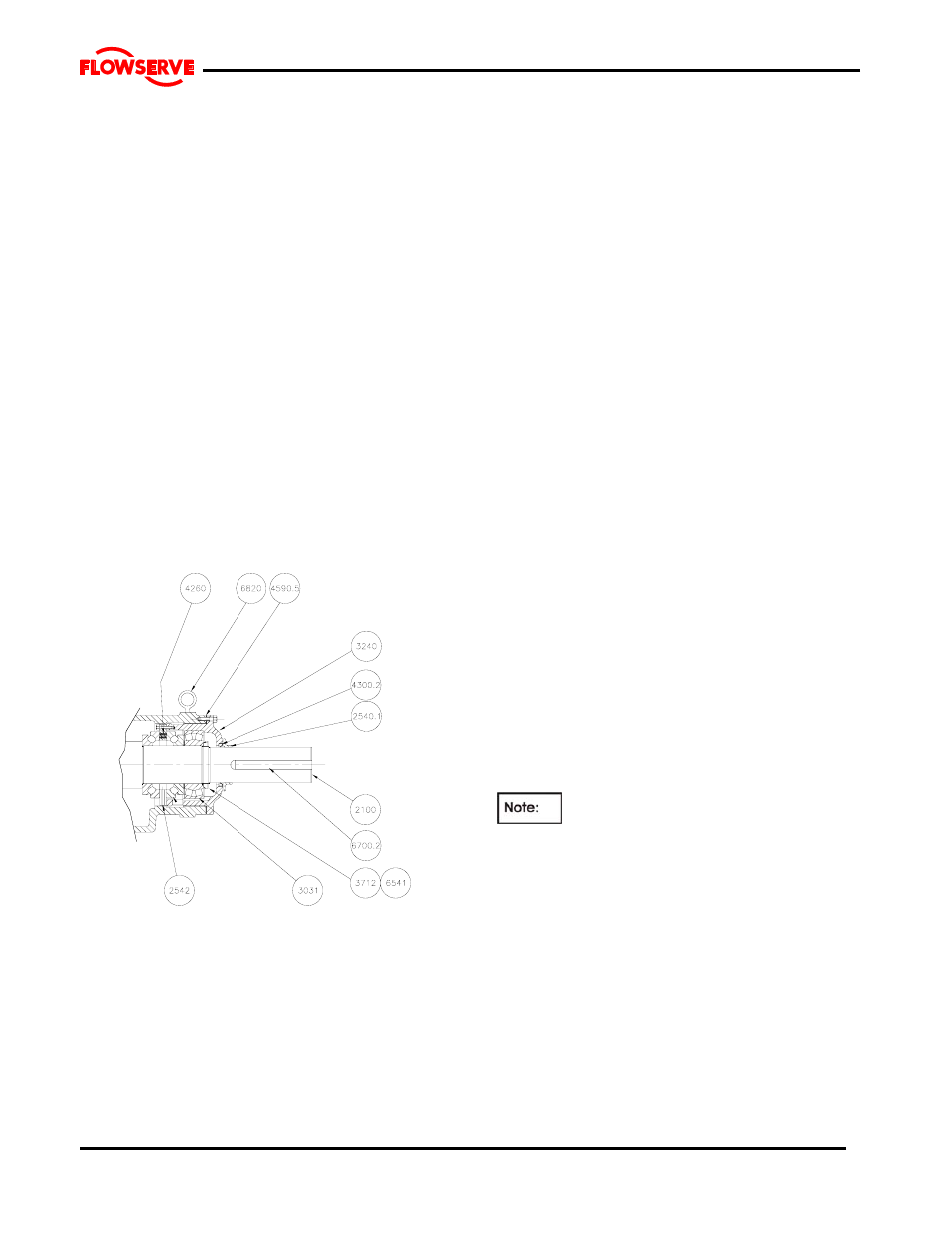
6.10.3.3 Frames 5&6
a) Place the shaft in a vertical position such that the
coupling end is up.
b) Lighting lubricate the shaft [2100] at the thrust
bearing position.
c) Install the inner race of one of the spherical roller
thrust bearing [3031] on the shaft. Use an induction
heater or hot oil bath to first heat the bearing (250
F recommended), press the bearing on the shaft
with the aid of a sleeve designed to push the inner
race only. Note that the bearing must remain
square to the shaft during assembly and that the
inner race must seat on the shaft shoulder.
d) Install the rollers and outer race onto installed inner
race.
e) Place the thrust bearing clamp ring [2542] on top of
the bearing installed.
f)Insert the springs [4260] into the holes provided in
the clamp ring.
g) Install the outer race of the second spherical roller
thrust bearing [3031] on top of the assembly. Place
3 - 0.010" spacer shims between the clamp ring
and one of the bearing outer races. Centralize the
loosely assembled bearing components. Using 2 c-
clamps or similar devices compress the springs in
the clamp ring.
h) Install the remaining inner bearing race using the
same procedure as above.
i) Install the bearing spacer [2460].
j) Install the radial bearing [3031].
k) Slide the bearing lock washers [6541] on the shaft
and fit the bearing locknut [3712]. Tighten the
locknut snugly and allow to cool. Check the
tightness. Before securing the lockwasher tab,
remove the spacer shims from the clamp ring.
Bend one tab on the lockwasher into a slot in the
locknut. Protect the bearings from contamination.
l) Carefully install the lip seal [4300] in the thrust
bearing housing [3240] by pressing it squarely into
the bore. The primary sealing lip (spring loaded) on
seal should be installed facing the bearing. A small
amount of sealant may be applied on the O.D. of
the seal prior to its installation.
m) Lubricate the inside bore of the thrust bearing
housing [3240] and assemble it over the thrust
bearings. Care must be taken to prevent damage
of the seal on the shaft.
6.10.4 Frame assembly
6.10.4.1 Frame 1 & 2
a) Place the pedestal with the large flange flat on a
work surface/table.
b)
Lift the bearing cartridge vertical and assemble to
the pedestal. Secure in position.
The orientation of the pedestal feet and the
tapped holes for the rear support foot should be
aligned.
c) Place the assembly so that the shaft when
installed will clear the table or work surface. The
assembly may be elevated if necessary.
d) Lift the shaft assembly into a vertical position (the
coupling end of the shaft is tapped for a lifting
bolt).
e) Lower it into the bearing frame [3122]. Note the
square head plug (or grease fitting in the thrust
bearing housing [3240] must align with the vent
plug [6521] in the frame [3122].
f) Install jacking and hold down hardware.
g) Place assembly horizontal and rest on pedestal
feet.
h) Install rear support foot for stability.