Flowserve M Slurry User Manual
Page 41
M SLURRY USER INSTRUCTION ENGLISH 71569241 - 02/08
Page 41 of 60
®
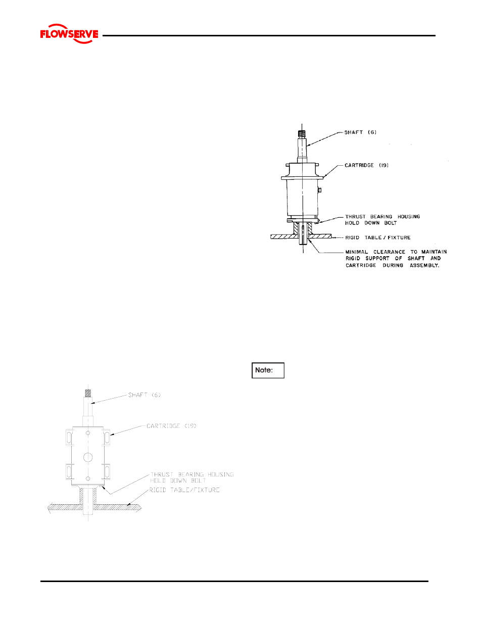
6.10.4.2 Frame 3& 4
a) Place the shaft assembly in a vertical position with
the thrust bearing housing [3240] resting on the
flange face and supported by blocks or clamps.
Access to one through hole in the thrust bearing
housing is required to attach one bolt.
i) Lift the bearing frame assembly [3122] vertically
and lower over the shaft assembly. Manually
guide the line bearing outer race into the bearing
frame bore. Note the square head plug (or grease
fitting in the thrust bearing housing [3240] must
align with the vent plug [6521] in the frame [3122].
j) Install at least one thrust bearing housing to
bearing frame hold down capscrews complete
with lockwasher to prevent the assembly from
coming apart when lifting.
k) Place the bearing frame assembly into a
horizontal position.
l) Install the remaining capscrews and lockwashers.
Assemble the jam nuts on the jacking screws and
assemble these into the thrust bearing housing
[3240].
m) Place pedestal on its feet.
n) Install cartridge assembly into the pedestal.
Secure with appropriate hardware.
o) Install rear support foot for stability.
6.10.4.3 Frames 5&6
a) Place the shaft assembly in a vertical position with
the thrust bearing housing [3240] resting on the
flange face. The shaft should be supported in a
fixture for safety and to prevent damage. Access
to one hole in the thrust bearing housing [3240] is
required to attach one bolt.
b) Install the gasket [4590.6] onto the housing
flange.
c) Lift the bearing cartridge [3122] vertically and
lower over the shaft assembly. Manually guide the
line bearing outer race into the bearing cartridge
bore. The thrust bearing housing [3240] and
cartridge [3122] are orientated to ensure that the
oil return slot in the thrust bearing housing [3240]
is properly located.
d) Install at least one thrust bearing housing to
bearing frame hold down capscrew complete with
lockwasher to prevent the assembly from coming
apart when lifting.
e) Install oil site glass [3856] and plugs in side of
bearing cartridge [3122].
f) Place the bearing frame assembly into a
horizontal position and mount unto the pedestal
rails.
g) The pedestal rails have sets of holes that will be
used to lock the pedestal in position. The outer
holes will be used for initial installation.
As the pump wears in service and the
impeller is readjusted the inner holes will be exposed
and the hold-down bolts will have to be moved.
h)
Install the remaining hold down capscrews and
lockwashers into the bearing housing [3240].
i)
Install the cartridge hold down bolts with the
heavy plate washers but do not tighten.
j)
Install the adjusting fixture [6569] between the ribs
of the bearing cartridge [3122]. The fixture may be
installed on either side of frame as convenient for
the installation.
6.10.5 Line Bearing Cover
6.10.5.1 Frames 1-4
a) Carefully install the lip seal [4300] in the line bearing
cover [3260] by pressing it squarely into the bore.
The primary sealing lip [spring loaded] on seal
should be installed facing the bearing. A small
amount of sealant may be applied on the O.D. of the
seal prior to its' installation.
b) Lubricate the o-ring [4610.1] and assemble into the
groove of the line bearing cover.