Flowserve M Slurry User Manual
Page 37
M SLURRY USER INSTRUCTION ENGLISH 71569241 - 02/08
Page 37 of 60
®
[3134] to the baseplate.
e) Remove the pedestal to casing bolts
f) Remove casing [1110] to expose the impeller [2200].
6.8.1.2 Frame 5 & 6
a) Loosen the bolts securing the bearing cartridge to
the pedestal. Do not remove bolts.
b) Using the adjusting fixture mounted between the ribs
on the bearing cartridge adjust the impeller back
towards the gland side wearplate until the impeller
makes light contact.
Excessive clamping force could damage
bearing races. Rotating the shaft helps to clear away
solids which may be trapped between the impeller and
stuffing box head.
c) Remove the pedestal to casing bolts.
d) Remove the casing [1110] to expose the impeller
[2200].
6.8.2 Stuffing
box
6.8.2.1 Shaft seal - gland packing
a) Remove gland nuts and gland halves [4120]
b) Remove gland packing rings [4130] and lantern
rings [4134] using a bent wire.
6.8.2.2 Shaft seal - mechanical seal
Refer to any special instructions supplied with
the mechanical seal.
a) Remove seal cover screws and pull off seal cover
complete with the stationary seal ring which is held
in place by the O-ring seal.
b) The mechanical seal cover can also be removed by
placing a wedge into the gland chamfer, as below:
6.8.2.3 Impeller and stuffing box
NEVER APPLY HEAT TO REMOVE IMPELLER
Trapped lubricant or vapour could cause an explosion.
Heat could also cause damage to the impeller.
a) Secure the stuffing box [4100] to the pedestal flange
using a pair of c-clamps or bolts if appropriate for
some sizes.
b) Adjust the impeller away from the gland side
wearplate.
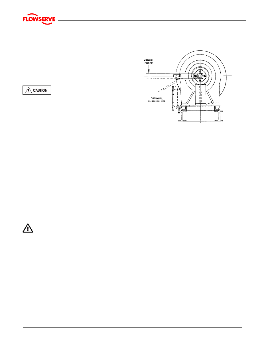
c) The impeller is threaded to the shaft and has been
self tightened to the shaft sleeve. To unscrew the
impeller the torque must be broken. It will be
necessary to either block the impeller or shaft at the
drive-end. A fixture similar to that shown in the
sketch below may be used. To unscrew the impeller
the shaft must be turned counter-clockwise.
d) On small pumps the impeller can be removed and
held by hand however, larger units will require that a
hoist be used to lift the impeller. Place a sling
through the impeller vanes.
e) Remove the impeller [2200].
f) Remove the expeller housing [4110] & expeller [250]
and/or stuffing box head [4100] as applicable to
pump construction.
g) Remove bolts securing bearing cartridge [3122] to
the pedestal [3120].
h) Remove bearing cartridge [3122].
6.8.3 Shaft sleeve
a) Remove the impeller spacer [2460] and shaft sleeve
gasket.
b) Remove the shaft sleeve [2445] if scored or worn.
6.8.4 Bearing housing
a) Remove the deflector [2540] and the line bearing
cover [3260].
b) Remove the pump half coupling and coupling key
[6700].
c) Remove the bearing frame support [3134] and
OHMM if applicable.
d) Lift the bearing frame assembly into a vertical
position with the thrust bearing housing [3240] up.
Rest the bearing frame flange on heavy wooden
blocks sufficiently high to ensure end of the shaft
does not come into contact with the floor or table.
e) Remove the thrust bearing hold down bolts and
remove shaft assembly for the bearing frame [3122].
6.8.5 Line bearing
a) Lay the shaft [2100] horizontal and support with
wooden ‘V’ Blocks.
b) Only if necessary remove the line bearing [3011]