Grouting, Initial alignment, Grouting (4.4) – Flowserve LNN User Manual
Page 14: Thermal expansion (4.5.1)
LNN, LNNV, LNNC USER INSTRUCTIONS ENGLISH 71569074 06-14
Page 14 of 56
flowserve.com
d)
The pump and driver have been aligned before
dispatch however the alignment of pump and motor
half coupling must be checked. If this is incorrect, it
indicates that the baseplate has become twisted
and should be corrected by re-shimming.
e)
Vertical pumps should be mounted following the
practices outlined for baseplate mounted pumps.
(Larger sizes may need the motor fitting after
installing the pump - refer to section 4.5.2.)
f) If the pump is driven via a universal joint drive
shaft there may be a requirement to offset the
pump shaft with respect to the driver to optimize
the universal joint drive shaft bearing life. This
offset will typically be in the range 0 to 4 degrees
depending on shaft design. Please consult the
separate User Instructions before installation.
g) Any support for the universal joint drive shaft
plummer blocks must not exhibit resonant
frequencies in the range 0.8 to 1.2 N where
N = pump running speed.
h) If not supplied, guarding shall be fitted as
necessary to meet the requirements of ISO
12100 and EN953 and or any applicable local
safety regulations.
4.4 Grouting
Where applicable, grout in the foundation bolts.
After adding pipe work connections and rechecking the
coupling alignment, the baseplate should then be
grouted in accordance with good engineering practice.
Fabricated steel, cast iron and epoxy baseplates can be
filled with grout. Folded steel baseplates should be
grouted to locate their packing pieces. If in any doubt,
please contact your nearest service centre for advice.
Grouting provides solid contact between the pump
unit and foundation prevents lateral movement of
running equipment and dampens resonant vibrations.
Foundation bolts should only be fully tightened when
the grout has cured.
4.5 Initial alignment
4.5.1
Thermal expansion
The pump and motor will normally
have to be aligned at ambient temperature and
should be corrected to allow for thermal expansion at
operating temperature. In pump installations
involving high liquid temperatures, the unit should be
run at the actual operating temperature, shut down
and the alignment checked immediately.
4.5.2
Alignment methods
Pump and driver must be isolated
electrically and the half couplings disconnected
.
The alignment MUST be checked.
Although the pump will have been aligned at the
factory it is most likely that this alignment will have
been disturbed during transportation or handling. If
necessary, align the motor to the pump, not the pump
to the motor.
Horizontal pumps – LNN and LNNC
Alignment is achieved by adding or removing shims
under the motor feet and also moving the motor
horizontally as required. In some cases where the
alignment cannot be achieved it will be necessary to
move the pump before recommencing the above
procedure. Alignment can be achieved by use of the
motor adjusters if fitted.
Vertical pumps
– LNNV
Adding or removing shims between the motor stool and
the pump casing achieves alignment. The motor/motor
stool assembly may also have to be moved horizontally
at the interface with the pump casing, as required.
On the frame mounted pumps angular alignment is
achieved by adding correctly sized shims to between
the motor stool and frame.
It should be noted that if the motor has a spigot (rabbet)
fit into the motor stool then it is not possible to achieve
any horizontal movement at this interface.
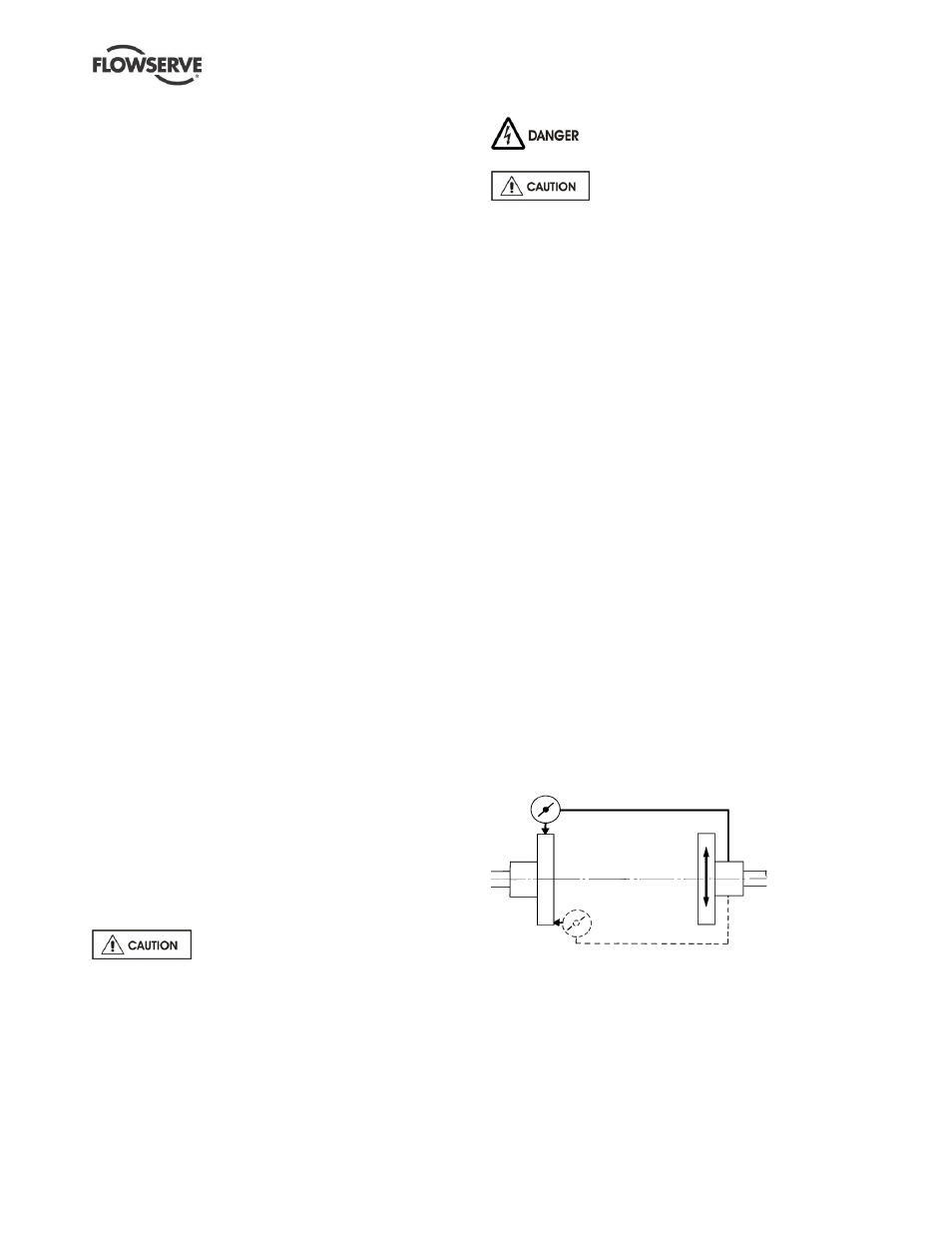
For couplings with narrow flanges use a dial indicator
as shown below to check both parallel and angular
alignment. The alignment values are maximums for
continuous service.
P a r a l l e l
A n g u l a r
Maximum permissible misalignment at working
temperature:
Parallel 0.2 mm (0.008 in.) TIR
Angular 0.1 mm (0.004 in.) TIR
When checking parallel alignment, the total indicator
read-out (TIR) shown is twice the value of the actual
shaft displacement. Align in the vertical plane first,
then horizontally by moving motor.