Stopping and shutdown, Hydraulic, mechanical and electrical duty, Hydraulic, mechanical and electrical duty (5.9) – Flowserve LNN User Manual
Page 25: Stopping and shutdown (5.8), 8 stopping and shutdown, 9 hydraulic, mechanical and electrical duty
LNN, LNNV, LNNC USER INSTRUCTIONS ENGLISH 71569074 06-14
Page 25 of 56
flowserve.com
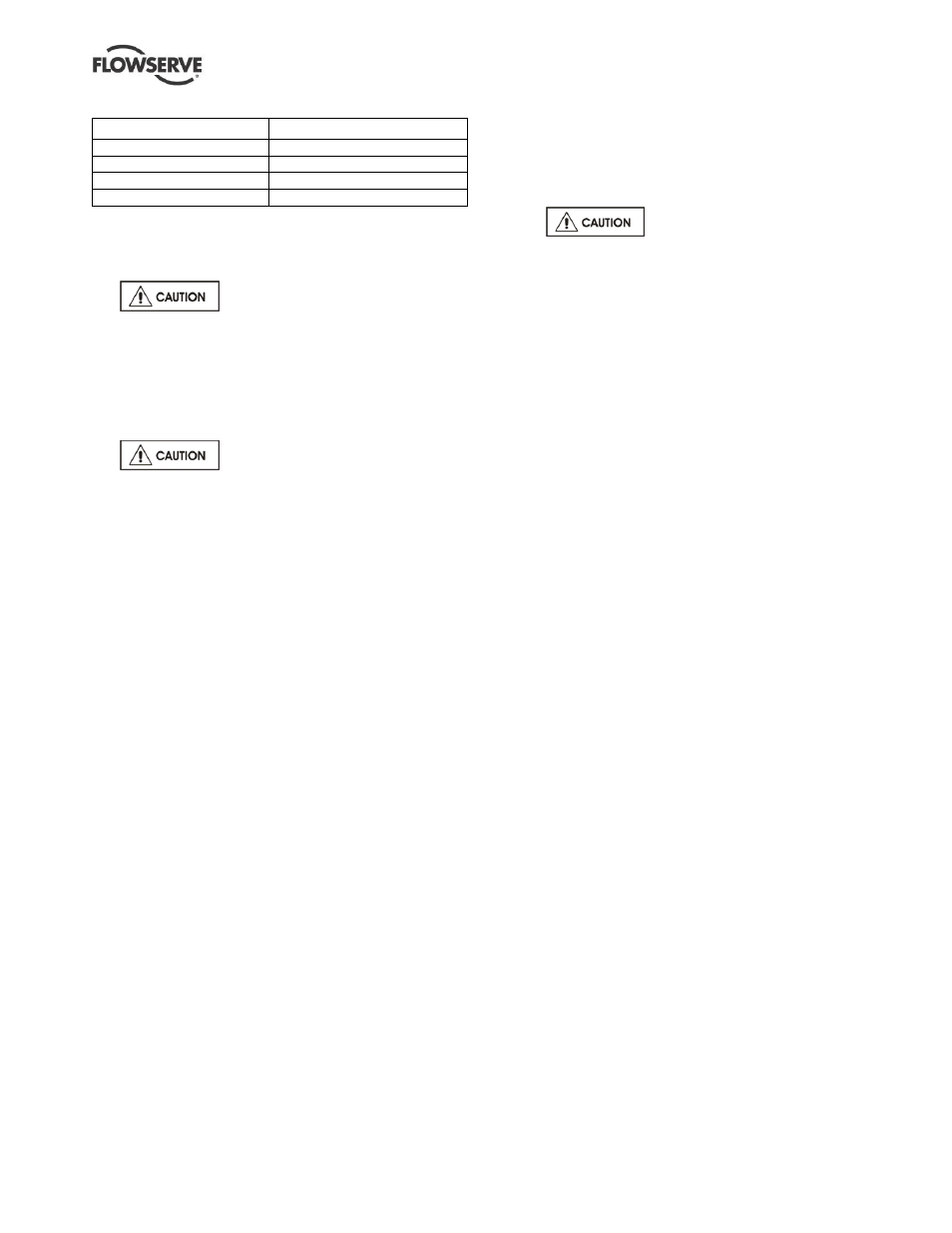
Motor rating kW (hp)
Maximum stop/starts per hour
Up to 15 (20)
15
Between 15 (20) and 90 (120)
10
90 (120) to 150 (200)
6
Above 150 (200)
Refer
Where duty and standby pumps are installed it is
recommended that they are run alternately every week.
5.8 Stopping and shutdown
a)
Close the outlet valve, but ensure
that the pump runs in this condition for no more
than a few seconds.
b) Stop the pump and Isolate the motor.
c) Switch off flushing and/or cooling/heating liquid
supplies at a time appropriate to the process. If the
pump is used on a water application keep it filled
with water otherwise drain the pump completely.
d)
For prolonged shut-downs and
especially when ambient temperatures are likely
to drop below freezing point, the pump and any
cooling and flushing arrangements must be
drained or otherwise protected.
e) If the pump is left to stand for an extended period
the pump shaft needs to be turned manually one
and one quarter (1 ¼) revolutions every week.
5.8.1
Flushing requirement
The hydraulic and or mechanical performance of pumps
exposed to water containing more than 500 ppm of
chloride can degrade due to accelerated corrosion
effects. In order to minimize these effects, Flowserve
recommend that the end user takes the following
precautions:
a) If the pump is going to be idle for 48 hours or
more, the suction and discharge valves on the
pump must be closed to isolate the pump
internals from the liquid pumped.
b) Open the casing drain connection (located on the
bottom of the lower half casing) to drain all the
water containing the chloride element from the
inside of the pump.
c) Close the casing drain connection and open the
casing fill connection (on the upper half of the
casing) to allow the casing to be filled with fresh
water containing no more than 50 ppm of
chloride.
d) Once the casing is full of fresh water, partially
close the drain connection while the fill
connection remains connected to the source of
fresh water. The casing must then be flushed for
a period of 1 hour.
e) Once flushing is completed, the drain connection
and fill connection must remain open. The inside
of the pump will be open to the atmosphere.
f) If the pump remains idle for 30 days or more, the
pump rotor must be turned.
g) When the pump is placed back into service, follow
the normal startup procedure. Take care not to
operate the pump with the suction valve closed.
5.8.1.1
Flushing limitations
The system designer and or the end user must
advise Flowserve of any chemical treatment that will
be added to the water.
If this process is not followed, the warranty terms of
the contract will be voided.
5.9 Hydraulic, mechanical and electrical
duty
This product has been supplied to meet the
performance specifications of your purchase order,
however it is understood that during the life of the
product these may change. The following notes may
help the user decide how to evaluate the implications
of any change. If in doubt contact your nearest
Flowserve office.
5.9.1
Specific gravity (SG)
Pump capacity and total head in meters (ft) do not
change with SG, however pressure displayed on a
pressure gauge is directly proportional to SG. Power
absorbed is also directly proportional to SG. It is
therefore important to check that any change in SG
will not overload the pump driver or over-pressurize
the pump.
5.9.2
Viscosity
For a given flow rate the total head reduces with
increased viscosity and increases with reduced
viscosity. Also for a given flow rate the power
absorbed increases with increased viscosity, and
reduces with reduced viscosity. It is important that
checks are made with your nearest Flowserve office
if changes in viscosity are planned.
5.9.3
Pump speed
Changing pump speed effects flow, total head, power
absorbed, NPSH
R
, noise and vibration. Flow varies in
direct proportion to pump speed, head varies as speed
ratio squared and power varies as speed ratio cubed.
The new duty, however, will also be dependent on the
system curve. If increasing the speed, it is important
therefore to ensure the maximum pump working
pressure is not exceeded, the driver is not overloaded,
NPSH
A
> NPSH
R
, and that noise and vibration are
within local requirements and regulations.