Flowserve LNN User Manual
Page 34
LNN, LNNV, LNNC USER INSTRUCTIONS ENGLISH 71569074 06-14
Page 34 of 56
flowserve.com
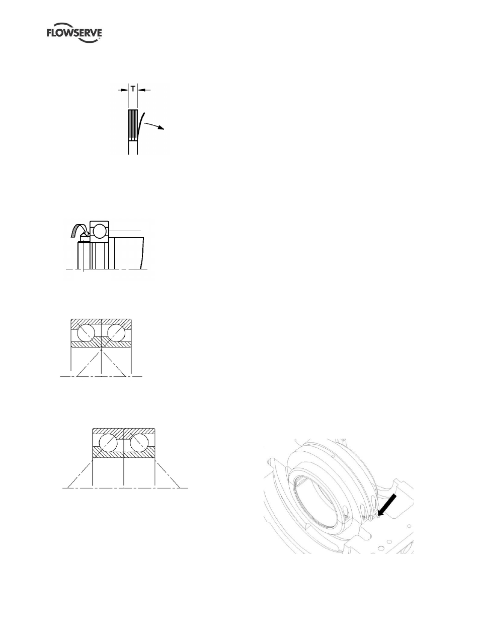
This allows the thickness to be varied in 0.05 mm
(0.002 in.) increments by peeling off layers to
achieve the required axial clearance.
j)
For oil lubricated units only, place shaft seal ring
[4305.3] in the shaft grooves for correct positioning.
k)
The bearing should be heated up to 100
C (212
F)
using a hotplate, hot oil bath or induction heater and
then slipped onto the shaft to the shoulder.
l)
On the thrust bearing side, mount the self-locking
ring type nut.
3011.1
3712
m) Standard bearing arrangements using a pair of
angular contact bearings will normally be
mounted with the shoulders of the inner rings
arranged face to face as shown as standard:
n) Some high temperature applications and other
special applications may use a pair of angular
contact bearings mounted in a back-to-back
arrangement as shown. Installation instructions
will be order specific.
6.10.6 Bearings - LNNV
a) Proceed as section 6.10.5 for the grease lubricated
ball thrust bearing at the drive end, ensuring shim
thickness is selected to give correct clearance.
b) If fitted with liquid lubricated bearing at non-drive
end press a new bearing bush [3300] into the lower
bearing housing [3200.1], making sure the face of
the bush is flush with the end of the housing.
c) Secure the lower bearing housing into the
stuffing box housing.
d) Slide the stuffing box housing, complete with bearing
bush, over the shaft and fit the O-ring [4610.6].
e) If fitted with optional grease lubricated bottom
bearing, slide liquid flinger assembly [2540.1;
4610.3; 6814.3] and bearing cover assembly
[3260.1; 2500] onto shaft.
f)
The bearing should be heated up to 100
C (212
F)
using a hotplate, hot oil bath or induction heater and
then slipped onto the shaft to the shoulder.
g) Secure to shaft with disc spacer [3645.1] and
circlip [6544.1].
6.10.7 Rotor unit
a) After completion of preceding steps, carefully
place the rotor into the lower half pump casing.
Make sure the fixing pins of the casing rings fit
correctly in the casing grooves and ensure correct
fit of locating pins at the stuffing box housing.
b)
Although both stuffing box housings are identical
the locating pins in the lower half casing are
different for drive and non-drive sides. The
stuffing box housing should be rotated so that the
correct slot engages with the pin. The long pin
with small diameter must engage in the small
deep slot whilst the short larger diameter pin
engages in the shallower wider groove.
6.10.7.1
LNN sleeve bearings
In case sleeve bearings are fitted in the pump follow
the following assembly steps:
c)
Fit the bearing bracket [3200.3] on the pump
lower half casing.
d)
Fit the bearing housing lower half [3200.1] on the
bearing bracket. Place the centering pin.
e) Fit the sleeve bearing lower half [3300] in the
housing. Ensure the anti-rotation pin is fitted in the
lower sleeve bearing half and locked in bearing
housing groove as shown in the picture below.
f)
Fit the lubrication oil ring on the sleeve bearing
(if provided).