Flowserve LNN User Manual
Page 17
LNN, LNNV, LNNC USER INSTRUCTIONS ENGLISH 71569074 06-14
Page 17 of 56
flowserve.com
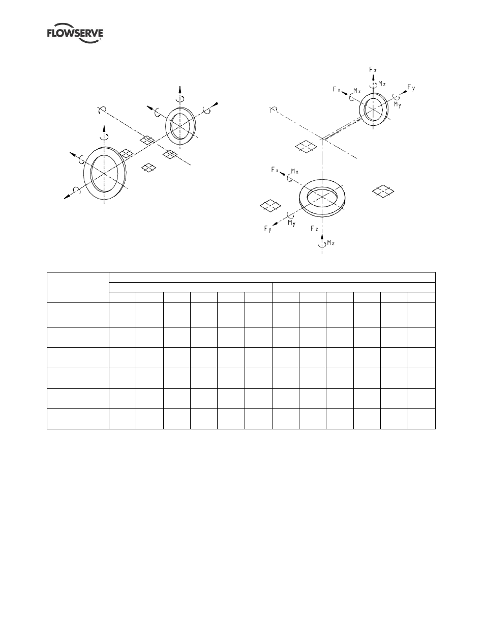
Load and momentum orientation of LNN and
LNNV pumps
Load and momentum orientation of LNNC pumps
Discharge
Suction
Pump
axis
4.6.2.2
LNNC maximum forces and moments allowed
Type and size
Maximum forces (F) in kN (lbf) and moments (M) in kNm (lbf
•ft)
Suction
Discharge
Fx
Fy
Fz
Mx
My
Mz
Fx
Fy
Fz
Mx
My
Mz
300-LNNC-475
and
300-LNNC-575
8.46
(1 900)
10.20
(2 290)
6.68
(1 500)
7.32
(5 380)
3.66
(2 690)
5.42
(3 990)
6.68
(1 500)
8.01
(1 800)
5.34
(1 200)
6.10
(4 490)
2.98
(2 190)
4.61
(3 390)
300-LNNC-500
7.12
(1 600)
8.90
(2 000)
5.79
(1 300)
6.37
(4 690)
3.12
(2 300)
4.75
(3 490)
6.68
(1 500)
8.01
(1 800)
5.34
(1 200)
6.10
(4 490)
2.98
(2 190)
4.61
(3 390)
350-LNNC-475 to
300-LNNC-900
10.70
(2 400)
12.90
(2 890)
8.58
(1 920)
9.12
(6 710)
4.90
(3 600)
6.74
(4 960)
7.12
(1 600)
8.90
(2 000)
5.79
(1 300)
6.37
(4 690)
3.12
(2 300)
4.75
(3 490)
600-LNNC-950
17.10
(3 840)
20.40
(4 580)
14.00
(3 140)
14.20
(10 450)
8.44
(6 210)
10.40
(7 650)
12.90
(2 890)
15.60
(3 500)
10.50
(2 360)
10.90
(8 020)
6.14
(4 520)
8.05
(5 920)
600-LNNC-975
14.90
(3 340)
17.80
(3 990)
12.10
(2 710)
12.40
(9 120)
7.22
(5 310)
9.14
(6 720)
12.90
(2 890)
15.60
(3 500)
10.50
(2 360)
10.90
(8 020)
6.14
(4 520)
8.05
(5 920)
700-LNNC-1225
19.30
(4 330)
23.00
(5 160)
15.90
(3 570)
15.90
(11 700)
9.65
(7 100)
11.70
(8 610)
14.90
(3 340)
17.80
(3 990)
12.10
(2 710)
12.40
(9 120)
7.22
(5 310)
9.14
(6 720)
Notes:
1) F = External force (tension or compression).
M = External moment, clockwise or counter-clockwise.
Sign convention follows ISO 1503 and ISO 13709/API610.
2) Forces and moments may be applied simultaneously in any
direction.
3) Values apply to all materials.
4) The nozzle loads applied to the pump flanges must not exceed
the values given in tables 4.6.2.1 and 4.6.2.2
5) Higher loads may be applicable, if direction and magnitude of
individual loads are known, but these need written approval
from Flowserve.
6) The pump nozzle is not to be used as a rigid support for the
piping line.
7) The piping loads applied to the pump flanges can be minimized
using the appropriate piping line supports.
8) The suction and discharge piping lines must not be connected
to the pump nozzle with an expansion joint (or similar flexible
pipes), unless they are rigidly blocked with tie rods.
9) Pumps must be on rigid foundations and baseplates must be
fully grouted.
10) Pump/baseplate should not be used as pipe anchor.
11) Suction and discharge piping should be anchored as close as
possible to the pump flanges to reduce vibration and prevent
strain on the pump casing. Expansion joints are
recommended. They must be properly tied and located on the
side of the pipe anchor away from the pump.
12) The pump mounting bolt torques specified must be used to
prevent relative movement between the pump casing and
baseplate. (See section 6.6, Fastener torques.) The bolt
material must have a minimum yield strength of 600 N/mm
2
(87 000 lb/in.
2
).
Failure to complying with the above can result in
damage to the pump.
DISCHARGE
SUCTION
Mx
My
Mz
Fx
Fy
Fz
Mx
My
Mz
Fx
Fy
Fz
PU
MP
AXIS