Flowserve LNN User Manual
Page 31
LNN, LNNV, LNNC USER INSTRUCTIONS ENGLISH 71569074 06-14
Page 31 of 56
flowserve.com
If optional bearing isolators or stationary labyrinths
are fitted in the bearing covers they can be
withdrawn complete with the covers. If replacement
is necessary they can be pressed out of the
respective covers. Take care not to damage O-ring
seals, when fitted, on shaft keyways etc.
c)
The bearing housings, ball bearings,
and shaft seals can be removed without removal
of the upper half casing, providing the pump is
fitted with a spacer coupling.
d) After unbolting the bearing housing, move it back
using a wedge, as below:
1214
3200
6.8.3
Line bearing
6.8.3.1
LNN and LNNC – drive end
Remove bearing [3011.2] from shaft using a bearing
puller ensuring pulling force is applied to the inner
race only.
6.8.3.2
LNNV – non-drive end
If the bearing bush is showing signs of wear it must
be removed by pressing out of the lower bearing
housing [3200].
If the non-drive end is fitted with the grease lubricated
ball bearing option, d
ismantle circlip [6544] and disc
spacer [3645] from the shaft and remove ball bearing,
[3011.2] for LNN or [3011.1] for LNNV, using a
bearing puller ensuring pulling force is applied to the
inner race only.
6.8.4
Thrust bearings
Unscrew and remove the self-locking bearing nut
[3712] and remove the bearing [3011.1] using a puller
as in 6.8.3.1 above.
On pumps with an un-sleeved shaft, check if a
bearing distance ring is fitted between the bearing and
the shaft shoulder. If so, this MUST be retained for
refitting during assembly.
6.8.5
Shaft seal - gland packing
a) Remove gland nuts [6580.2] and gland [4120].
b) Lever out gland ring [4131] using its grip groove.
c) Remove gland packing [4130] and lantern rings
[4134] using a bent wire.
6.8.6
Shaft seal - component mechanical seal
Refer to any special instructions supplied with
the mechanical seal.
a)
Remove seal cover screws [6570.7] and pull off
seal cover [4213] complete with the stationary
seal ring that is held in place by the O-ring seal.
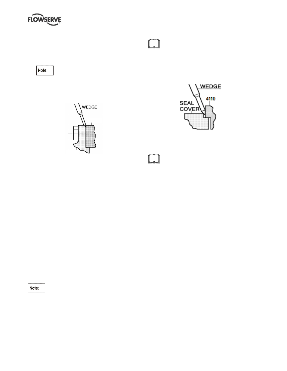
b)
The mechanical seal cover can also be removed by
placing a wedge into the gland chamfer, as below:
c) Mechanical seal assembly [4200.1] can now be
removed.
6.8.7
Shaft seal
– cartridge mechanical seal
If fitted with optional cartridge mechanical seal,
refer to any separate user instructions supplied.
Remove nuts [6580.2] to detach seal assembly from
stuffing box housing [4110] and slide off complete
seal assembly [4200].
6.8.8
Shaft sleeve
6.8.8.1 LNN, LNNC both ends and LNNV drive end
a) Loosen grub screw [6814.2] and unscrew shaft
nut [2910]. Remove shaft sleeve [2450] using its
pulling groove.
b)
If after removing the seal cover, or cartridge seal,
there is no shaft nut [2910] visible, this means
that an unsleeved shaft is fitted. (See sectional
drawing for details.)
c)
The shaft nut and spacer are accessible after
removing the stuffing box housing [4110] and
should be removed as described in a) above.
6.8.8.2
LNNV non-drive end
a) Remove capscrew [6579] and end cap [6415]
from shaft end.
b) Remove lower bearing sleeve [3400] and lower
sleeve [2400].
c) If fitted with optional grease lubricated ball
bearing the shaft sleeve should be removed as
detailed in section 6.8.8.1.
6.8.9
Impeller and wear rings
a) The impeller and wear rings can now be removed
if required.