Flowserve LNN User Manual
Page 33
LNN, LNNV, LNNC USER INSTRUCTIONS ENGLISH 71569074 06-14
Page 33 of 56
flowserve.com
b) The rotor always rotates towards the expanding
section of the volute.
c)
The two shaft sleeves and shaft nuts clamping
the impeller define its position on the pump shaft
and hence in the pump casing.
d) The correct axial position of the impeller and
mechanical seals can be checked with the
grooved checking marks on the pump shaft.
6.10.3 Shaft seal - packed gland
a) Fit impeller key and slide impeller onto shaft.
b)
Insert O-ring into shaft sleeves and slide sleeves
along shaft and into the impeller hubs. Lightly
lubricate the shaft and O-ring for easier assembly.
N
o O-rings are fitted beneath
LNNV product lubricated bearing sleeves (see
sectional drawing). On unsleeved shaft versions
an O-ring is fitted at each end of the spacer.
c) Tighten and adjust shaft nuts so that their distances
to the grooved marks are equal at both ends.
d)
Lock the shaft nuts in place with grubscrews.
Tighten capscrew (LNNV).
e)
Slide the stuffing box housings over the shaft and
fit the O-ring [4610.6].
This O-ring must be replaced at
each and every dismantling.
f)
Place the gland ring [4131] over the sleeve.
6.10.4 Shaft seal - component mechanical seal
Refer to any special instructions supplied with
the mechanical seal.
a) Slide the rotating assembly of the mechanical seal
along the shaft sleeve until the retaining ring has
reached the correct setting distance along the sleeve.
Tighten the grub screws to lock it into position.
b) Insert O-ring into shaft sleeves and slide sleeves
along shaft and into the impeller hubs. Lightly
lubricate the shaft and O-ring for easier assembly.
c) Tighten and adjust shaft nuts so that the distances
to the grooved marks are equal at both ends.
d)
Lock the shaft nuts in place with grub screws.
Tighten cap 7screw (LNNV).
e)
Slide the stuffing box housings over the shaft and
fit the O-ring [4610.6].
This O-ring must be replaced at
each and every dismantling.
f)
Slip the mechanical seal covers [4213] together
with their installed stationary seal parts and O-rings
over the shaft.
g) If cartridge mechanical seals are to be fitted.
Refer to any special instructions supplied
with the mechanical seal. Cartridge seals are
usually fitted direct to the pump shaft as shown in
section 8.1.2.
6.10.5 Ball bearings - LNN, LNNC
Before mounting the bearings, proceed as follows:
a)
Fit the shaft seal rings [4305.1] onto the shaft
and slide the bearing cover [3260.1] over the
shaft. If supplied also fit shaft seal ring [4305.3]
into shaft.
b) Pumps with grease lubricated bearings have V-ring
seals on the outside of the bearing cover only.
Pumps with oil lubricated bearings have, in addition,
shaft seal rings [4305.3 and 4305.4] on the inside
of the bearing covers. If V-rings are fitted, the inner
V-rings have two small perforations in the lip. Inner
V-rings engage in the grooves in the shaft.
c)
If new optional bearing labyrinth seals are to be
fitted, press them into their respective covers
before the covers are assembled to the shaft.
Take care not to damage O-ring seals. Ensure
liquid flinger [2540] is fitted to shaft before
bearing cover [3260.1] is slid onto the shaft.
d)
If new optional bearing isolators are to be
fitted in the bearing covers refer to separate
instructions supplied with the isolators.
e)
Determine the thickness of the laminated shim on
the thrust bearing side. Provisionally position the
bearing into the bearing housing seated against
the circlip and thrust washer.
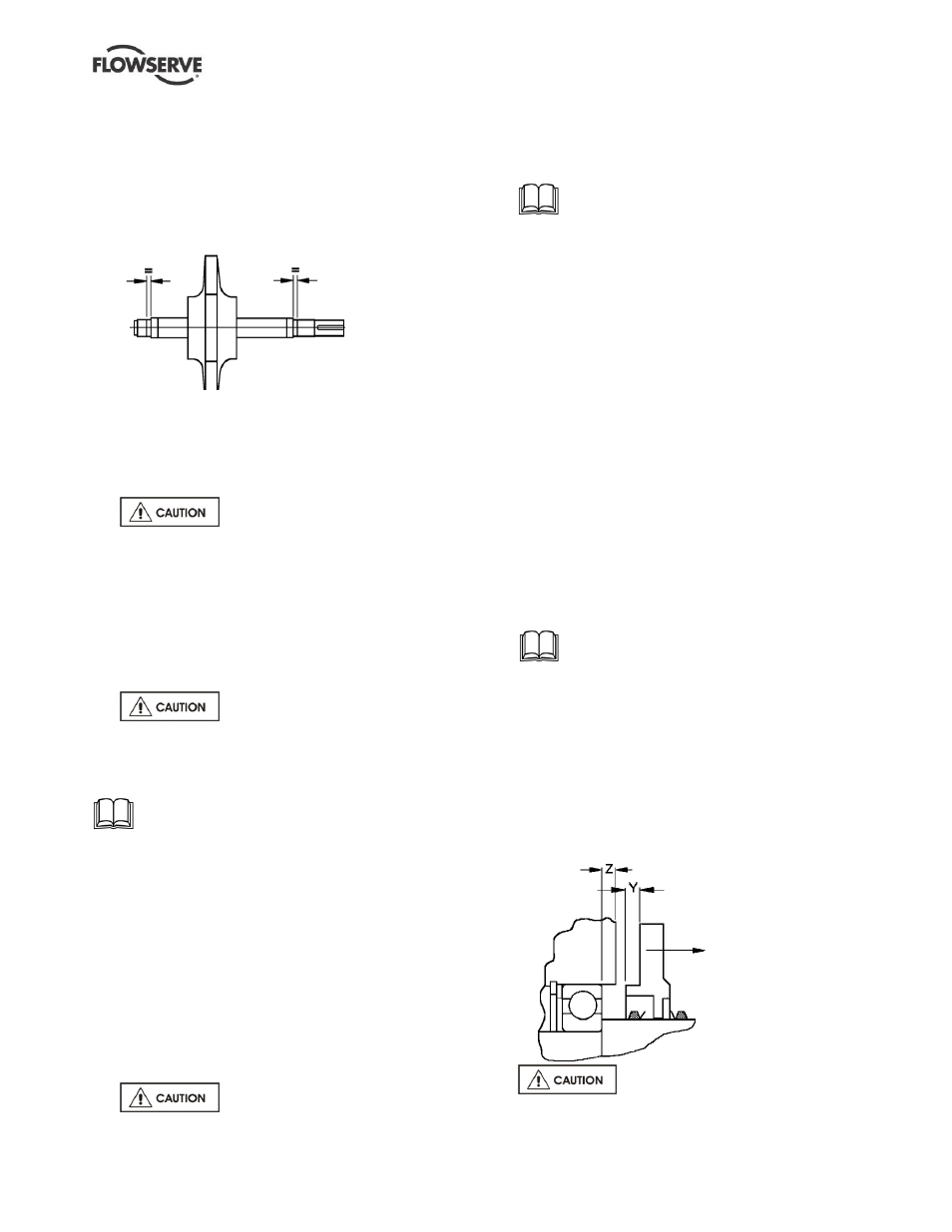
f)
Measure distance 'Y' on the bearing cover.
g)
Measure distance 'Z' to face of bearing housing.
h)
Shim thickness to give correct clearance will be
'Y' minus 'Z' = 0.1 to 0.2 mm (0.004 to 0.008 in.)
Place correct shims on the shaft.
i)
The shim is laminated material with
an original thickness (T) of 1.0 mm (0.039 in.) and
laminate thickness of 0.05 mm (0.002 in.).