Flowserve LNN User Manual
Page 36
LNN, LNNV, LNNC USER INSTRUCTIONS ENGLISH 71569074 06-14
Page 36 of 56
flowserve.com
b) On oil lubricated units ensure that the shaft seal
rings [4305.3] are located in the grooves in the
shaft.
c)
Slip the bearing housings over their respective
bearings and insert them into the recesses of the
pump casing.
d)
Fit bearing housing setscrews [6570.4] and tighten.
e)
Apply liquid sealant to bearing cover flange.
f)
Ensure correct seating of shim.
g)
Turn bearing cover to correct position:
For grease lubricated units – the grease nipple
can be found towards the top half of the bearing
casing.
For oil lubricated units – the oil plug sits towards
bottom half of the bearing casing.
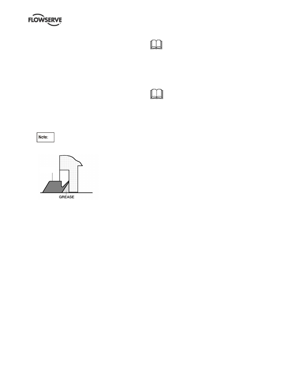
h) Tighten bearing cover at bearing housing and
push the shaft seal ring [4305.1] against the
bearing cover.
The sealing surface of the shaft seal ring
must be covered with grease and pushed gently
up to the bearing cover, otherwise it may run hot!
4 3 0 5 . 1
i)
Refit plugs, vents, oiler etc. as applicable.
j)
On oil lubricated units at the drive end, place
the
shaft seal ring [4305.4] over the shaft and position
in the groove to seal against the end cover.
k) Fit the end cover [3260.2] and the
shaft seal ring
[4305.2], lubricate it with grease and push it up to
the end cover.
l)
At the non-drive end, fit the bearing end cover
[3266] and tighten the screws [6570.5].
6.10.9.1
LNN shaft driven pump (if required)
m) Place the key [6700.5] in the groove and connect
the coupling [3810.2].
n) Reconnect the shaft driven pump [3810.1].
o) Connect the suction and discharge flange to the
suction and discharge skid line.
p) Ensure the axial probes wires are not in contact
with coupling hub
6.10.10 Stuffing box assembly
6.10.10.1
Gland packing
Insert inner two rings of packing, then lantern ring
halves and finally 2 or 3 more rings of packing.
Loosely fit the gland [4120] and connect flush line.
6.10.10.2
Component mechanical seal [4200.1]
Refer to separate User instructions supplied
with the mechanical seal
.
Fasten seal covers [4213] complete with O-ring
[4610.9] using screws [6570.7]. Connect flush line.
Connect any auxiliary piping.
6.10.10.3
Cartridge mechanical seal [4200]
If optional cartridge seals are fitted, refer to
separate User instructions supplied with the seal, for
securing and activating the seal.