Flowserve LNN User Manual
Page 35
LNN, LNNV, LNNC USER INSTRUCTIONS ENGLISH 71569074 06-14
Page 35 of 56
flowserve.com
g) Fit the sleeve bearing upper half with pin and
screws as shown in the above picture
h) Put the bearing housing upper half and its screw
[6570.7].
6.10.8 Casing gasket
a)
The gasket must be cut from asbestos-free sheet
material of 0.8 + 0.1/-0.05 mm (
1
/
32
in.) thickness,
by following the actual inner casing contour of the
lower half casing.
b)
Special care must be exercised at the bores and
stuffing box housing.
c)
The gasket must be accurately cut and fit flush
with these bores to prevent leakage at the O-ring.
d)
Position gasket carefully onto the cleaned
surface of the lower half casing.
e)
Coat the casing bottom half flange surface of the
wall between suction and discharge side with a
contact adhesive, as below:
1 5 0 0
To assist assembly, particularly on larger
sizes it may be advisable to use further adhesive
at key points around this flange.
f) Push gasket flush against fit of stuffing box
housing and secure gasket locally again using
the above adhesive paste.
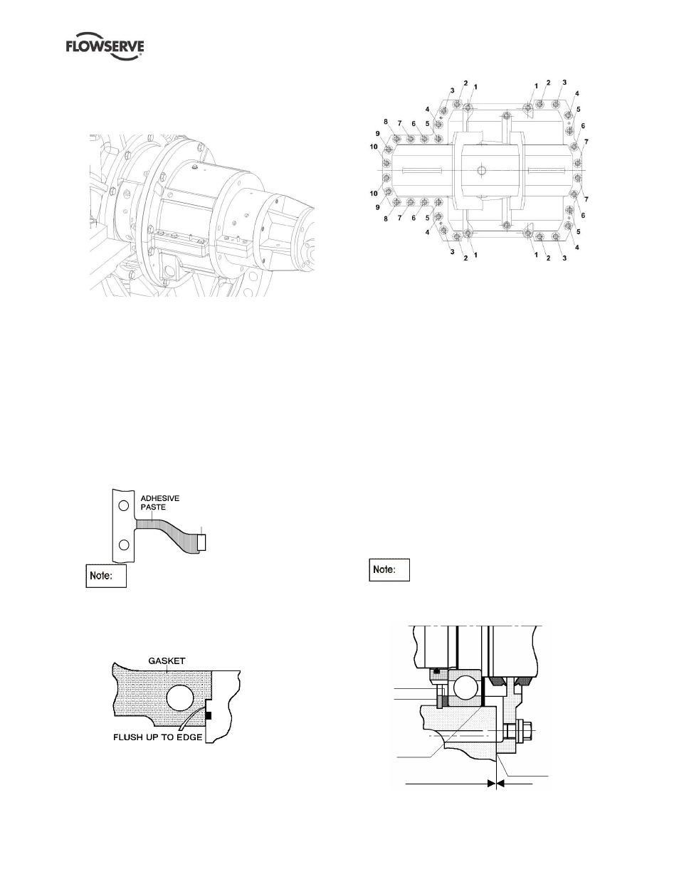
g) Place upper half casing onto pump, ensuring
dowels or stuffing box and bearing housing make
correct alignment
h)
Tighten upper half casing flange nuts/screws
according the following order:
Torque the nuts in 2 or more complete passes of
increasing torque values until the recommended
values are achieved.
First pass:
50 % of specified torque
Second pass: 100% of specified torque value
6.10.8.1
LNN tilting pad thrust bearings
In case a tiling pad thrust bearings is fitted in the
pump follow the following assembly steps.
i)
Ensure the thrust floating rings [4243] are set on
the shaft.
j)
Fit the [3031.1] thrust disc on the shaft.
k) Install the [3031.2] titling pads with its
temperature element (if provided) in the bearing
housing lower half.
l)
Set the filler plate [3126] and appropriate shims.
The total recommended end play for the thrust
bearing shall be set between 0.23 mm (0.009 in)
to 0.30 mm (0.12 in).
6.10.9 Bearing housing
a) Insert the circlip [6544] and disc spacer [3645] at
the thrust bearing end.
The circlip and thrust washer must not
be fitted at the line bearing end.
LNN and LNNC - thrust bearing at non-drive end.
LNNV - thrust bearing at drive end.
3 6 4 5
6 5 4 4
3 1 2 6
S H I M
0.1 to 0.2 mm
(0.004 to 0.008 in.)
LIQUID
SEALANT
Clearance between bearing outer race
and bearing cover