Flowserve LPNV Worthington User Manual
Page 18
LPNV USER INSTRUCTIONS ENGLISH 87900031 – 06/14
Page 18 of 48
4.3 Installation and alignment
Normally the pump and motor stand are shipped
mounted on the soleplate, whereas the motor is
sent separately.
4.3.1 Pump
-
Clean all debris from pump and foundation
before making the installation
-
Lift pump assembly using lifting lugs provided
on motor stand.
-
Slowly lower pump onto foundation guiding
pump until discharge and suction nozzles face
proper direction to mate with discharge and
suction piping respectively, and soleplate
mounting holes align with foundation bolts.
-
Seat pump on foundation and level, using
shims under pump soleplate at each foundation
bolt. The levelling tolerance is 0.4 mm/m (0.005
inch per foot), to be checked in both directions
on machined surfaces.
-
Uniformly tighten foundation bolts.
-
Connect suction and discharge piping to pump
flanges taking care that no excessive strains
are applied to pump nozzles.
-
Recheck leveling tolerance. Any eventual
distortion affecting the alignment must be
corrected by varying shims between
soleplate and foundation.
- Ensure that shaft alignment per Section 4.3.3
can be achieved prior to grouting the soleplate.
4.3.2 Electric motor
-
Fit half coupling on pump shaft, if not already
fitted.
-
Install driver half of coupling on motor shaft.
-
Lift motor and center over pump shaft.
-
Slowly lower motor onto motor stand making
certain that mounting holes in motor flange and
motor stand are aligned.
During pump assembly at
factory, the pump shaft is axially positioned by
the adjusting nut so that the impeller is
centered in respect of the casing volute, and
the space between coupling halves is as
specified on pump elevation drawing.
Make certain that above value is maintained. If
necessary, rotate the adjusting nut to lift or
lower the pump rotor.
When the pump is provided with
mechanical seal, the shaft collar drive screws
must be loosened prior to
screwing/unscrewing of the adjusting nut.
Driver and driven shafts should
not be rotated unless bearings are pre-
lubricated before aligning starts.
4.3.3 Alignment of spacer - couplings
-
Check the gap between the coupling halves
against the dimensions shown on the elevation
drawing or as stamped on the coupling hub.
For any necessary adjustment move the driver
rather than the driven machine.
-
Using the coupling nut or the draw holes, clamp
on the driven machine half-coupling a suitable
extension arm or bracket sufficiently long to
extend across the space between the driven
machine and driver coupling hubs.
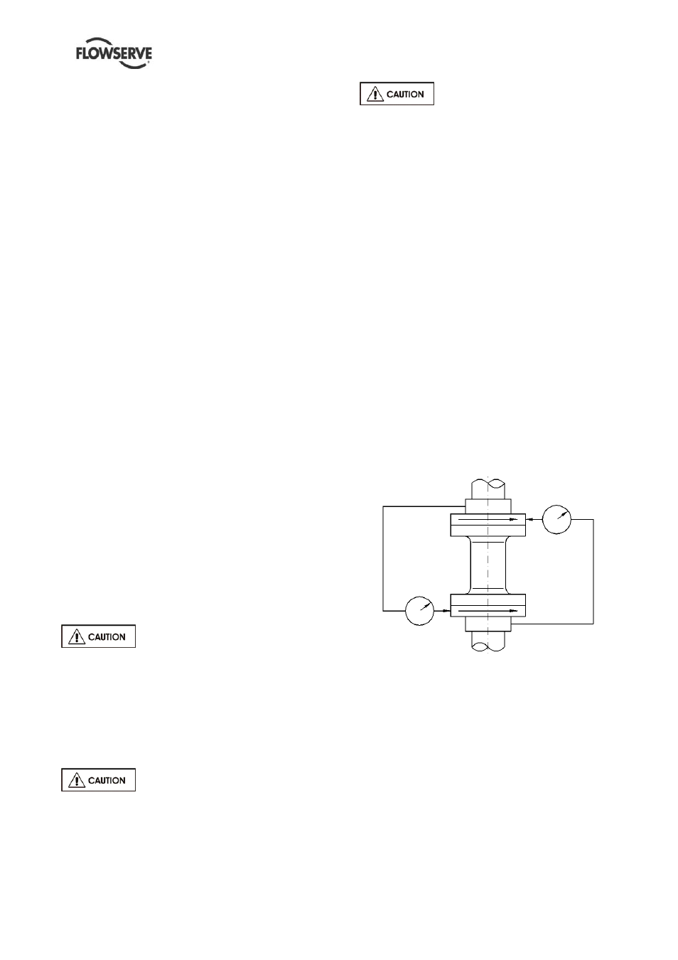
Attach to the bracket as shown in Fig.4.3 a dial
indicator with the probe resting on the outer
diameter of the driver half-coupling to check
both parallel and angular alignment.
For angular alignment rotate both the driver
and driven shafts together making sure that the
indicator probe always rests on the same point.
Take readings at every quarter turn.
For parallel alignment rotate the driven shaft
with the probe resting on the O.D. of the driver
half-coupling. Take readings at every quarter
turn.
For detailed alignment procedure refer to API
RP686.
Figure 4.3
Maximum permissible misalignment at working
temperature:
Parallel 0.05 mm (0.002 in.) TIR
Angular
0.05mm/100mm
(0.0005In/In)
- Recheck alignment by reversing bracket and
repeating angular and parallel check readings
-
Assemble coupling-spacer as per the
manufacturer's instructions.