Flowserve LPNV Worthington User Manual
Page 6
LPNV USER INSTRUCTIONS ENGLISH 87900031 – 06/14
Page 6 of 48
1.6.4.2 Marking
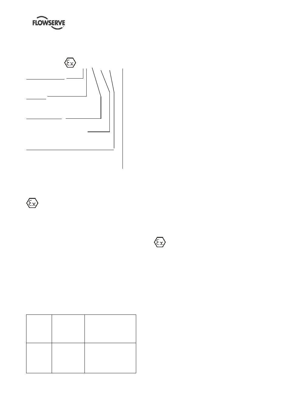
An example of ATEX equipment marking is shown
below. The actual classification of the pump will be
engraved on the nameplate.
II 2 GD c IIC
135 ºC (T4)
Equipment Group
I = Mining
II = Non-mining
Category
2 or M2 = High level protection
3 = normal level of protection
Gas and/or Dust
G = Gas; D = Dust
C = Constructional safety
(in accordance with En13463-5)
Gas Group
(Equipment Category 2 only)
IIA – Propane (typical)
IIB – Ethylene (typical)
IIC – Hydrogen (typical)
Maximum surface temperature (Temperature
Class) (See section 1.6.4.3.)
1.6.4.3 Avoiding excessive surface
temperatures
ENSURE THE EQUIPMENT
TEMPERATURE CLASS IS SUITABLE FOR THE
HAZARD ZONE
Pumps have a temperature class as stated in the
ATEX Ex rating on the nameplate. These are
based on a maximum ambient of 40 °C (104 °F);
refer to Flowserve for higher ambient
temperatures.
The surface temperature on the pump is
influenced by the temperature of the liquid
handled. The maximum permissible liquid
temperature depends on the temperature class
and must not exceed the values in the table that
follows.
The temperature rise at the seals and bearings
and due to the minimum permitted flow rate is
taken into account in the temperatures stated.
Temperature
class to
EN 13463-1
Maximum
surface
temperature
permitted
Temperature limit of liquid
handled (* depending on
material and construction
variant - check which is
lower)
T6
T5
T4
T3
T2
T1
85 °C (185 °F)
100 °C (212 °F)
135 °C (275 °F)
200 °C (392 °F)
300 °C (572 °F)
450 °C (842 °F)
Consult Flowserve
Consult Flowserve
115 °C (239 °F) *
180 °C (356 °F) *
275 °C (527 °F) *
400 °C (752 °F) *
The responsibility for compliance with the
specified maximum liquid temperature is with
the plant operator.
Temperature classification “Tx” is used when the
liquid temperature varies and the pump could be
installed in different hazardous atmospheres. In
this case the user is responsible for ensuring that
the pump surface temperature does not exceed
that permitted in its actual installed location.
If an explosive atmosphere exists during the
installation, do not attempt to check the direction of
rotation by starting the pump unfilled. Even a short
run time may give a high temperature resulting
from contact between rotating and stationary
components.
Where there is any risk of the pump being run
against a closed valve generating high liquid and
casing external surface temperatures it is
recommended that users fit an external surface
temperature protection device.
Avoid mechanical, hydraulic or electrical overload
by using motor overload trips, temperature monitor
or a power monitor and make routine vibration
monitoring checks.
In dirty or dusty environments, regular checks
must be made and dirt removed from areas around
close clearances, bearing housings and motors.
1.6.4.4 Preventing the build up of explosive
mixtures
ENSURE THE PUMP IS PROPERLY
FILLED AND VENTED AND DOES NOT RUN
DRY.
Ensure the pump and relevant suction and
discharge pipeline system is totally filled with liquid
at all times during the pump operation, so that an
explosive atmosphere is prevented. In addition it is
essential to make sure that seal chambers,
auxiliary shaft seal systems and any heating and
cooling systems are properly filled.
If the operation of the system cannot avoid this
condition the fitting of an appropriate dry run
protection device is recommended (eg liquid
detection or a power monitor).
To avoid potential hazards from fugitive emissions
of vapor or gas to atmosphere the surrounding
area must be well ventilated.