Flowserve LPNV Worthington User Manual
Page 35
LPNV USER INSTRUCTIONS ENGLISH 87900031 – 06/14
Page 35 of 48
6.7.2 Thrust bearing disassembly
Disassemble the thrust bearing as follows:
a) Unbolt and remove cover from thrust bearing
housing.
b) Remove springs and shaft guide bushing
complete with line bearing, locking nut and thrust
bearing.
c) Unscrew locking nut and pull out the upper thrust
bearing.
d) Remove the shaft nut and pull out the bottom
thrust bearing.
6.7.3 Shaft seal - gland packing
a) Remove gland nuts and gland.
b) Lever out gland ring using its grip groove.
c) Remove gland packing rings and lantern rings
using a bent wire.
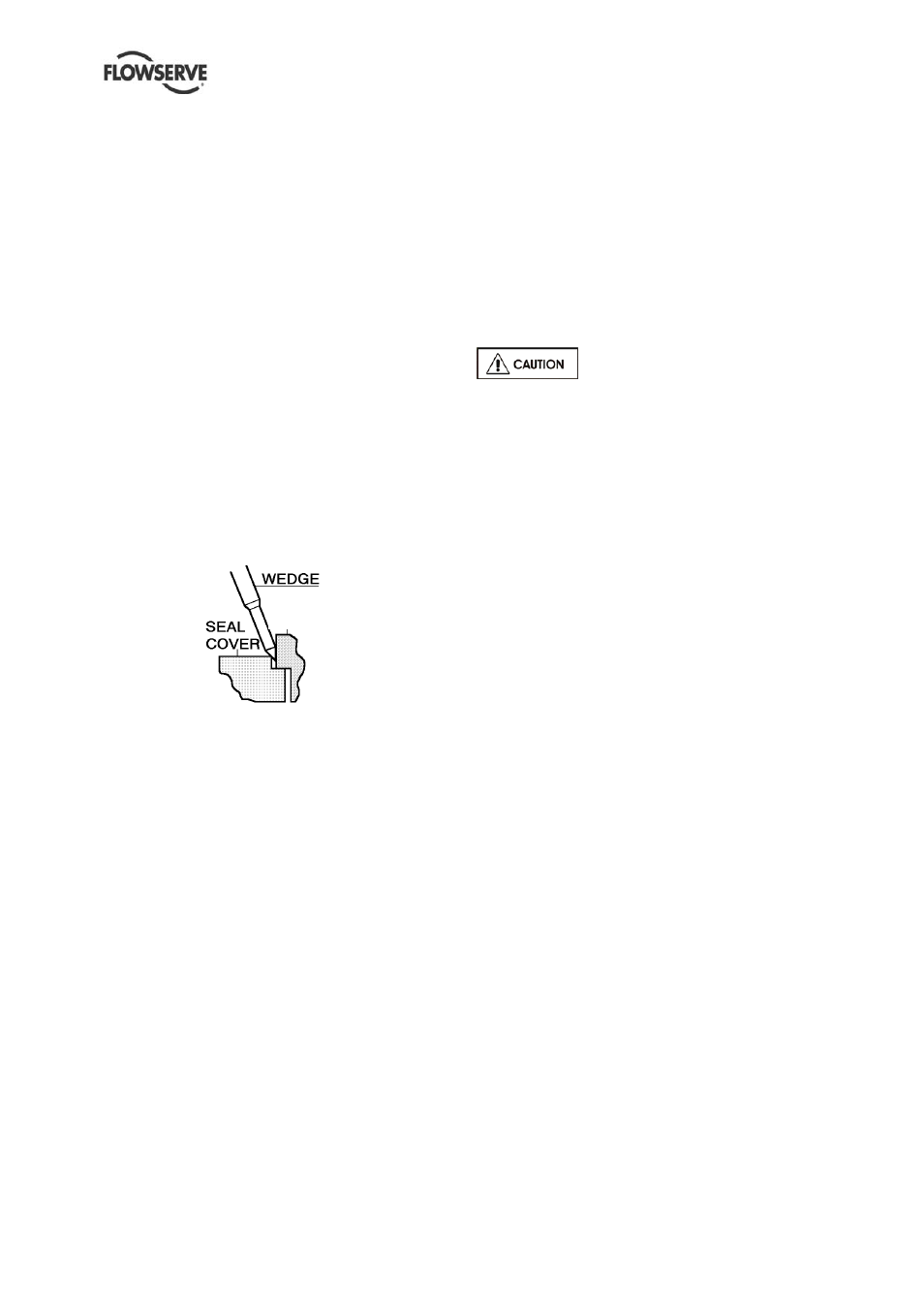
6.7.4 Shaft seal - mechanical seal
d) Remove seal cover screws and pull off seal
cover complete with the stationary seal ring
which is held in place by the O-ring seal.
e) The mechanical seal cover can also be removed
by placing a wedge into the gland chamfer, as
below:
Refer to any special instructions supplied
with the mechanical seal.
6.7.5 Rotor disassembly
Disassemble the rotor as follows:
a) Remove throttle bushing and casing rings.
b) Unscrew locking nut and remove impeller and
impeller key.
c) Slide out shaft sleeve and remove locating ring in
two halves.
6.8 Examination of parts
As the pump and rotor are dismantled, all individual
parts, all important joints and all wearing surfaces
should be carefully examined. As a general rule,
regardless of the performance of the unit, parts
appreciably worn should be renewed if it is not
intended to examine the pump until the next
overhaul period. It should be remembered that when
parts in new or good condition with metal seats are
assembled in contact with dirty or worn parts, the
new parts are very likely to wear out rapidly.
Used parts must be inspected before
assembly to ensure the pump will subsequently run
properly.
In particular, fault diagnosis is essential to enhance
pump and plant reliability.
6.8.1 Half casings
a) Inspect for excessive wear, pitting, corrosion,
erosion or damage and any sealing surface
irregularities. New casing gasket should be
installed whenever the pump is disassembled.
Remove all traces of all gasket material. When
using any tool to remove gasket material, take
great care not to damage the machined
surfaces.
b) Replace as necessary.
6.8.2 Impeller
a) Remove worn impeller rings by mechanical
turning.
Slightly eroded parts can be repaired by welding.
Dynamically balance impellers after any machine
work. To balance remove metal from the front or
back shroud of the impeller at the point of
unbalance.
6.8.3 Mechanical seal (if fitted)
a) Mechanical seal stationary and rotating faces
should be inspected for signs of wear or cracks
and replaced as necessary.
b) It is recommended that when reassembling
mechanical seal new "O" rings and gaskets be
used.
c) Refer to manufacturers drawing for assembly of
mechanical seal. Refer to mechanical seal
section within this manual for further details.
6.8.4 Bearing housing
Thoroughly flush and clean the oil passages, then
coat the inner surfaces with a thin film of lubricating
oil.
Cover the bearing body to keep it clean until ready
for installation.