Flowserve LPNV Worthington User Manual
Page 21
LPNV USER INSTRUCTIONS ENGLISH 87900031 – 06/14
Page 21 of 48
4.4.2 Suction Piping
a) The inlet pipe should be one or two sizes
larger than the pump inlet bore and pipe bends
should be as large radius as possible.
b) Keep the suction pipe free of all air pockets.
(Vent is required).
c) Pipework reducers should have a maximum
total angle of divergence of 15 degrees.
d) Use only eccentric reducers with the straight
side on the top.
e) Flow should enter the pump suction with
uniform flow, to minimize noise and wear.
f) A gate valve is recommended in the suction
line.
g) Except if considerable foreign matter is
expected strainers are not recommended in
inlet piping. Inlet strainers, when used, should
have a net “free area” (see section 4.4.2.1)
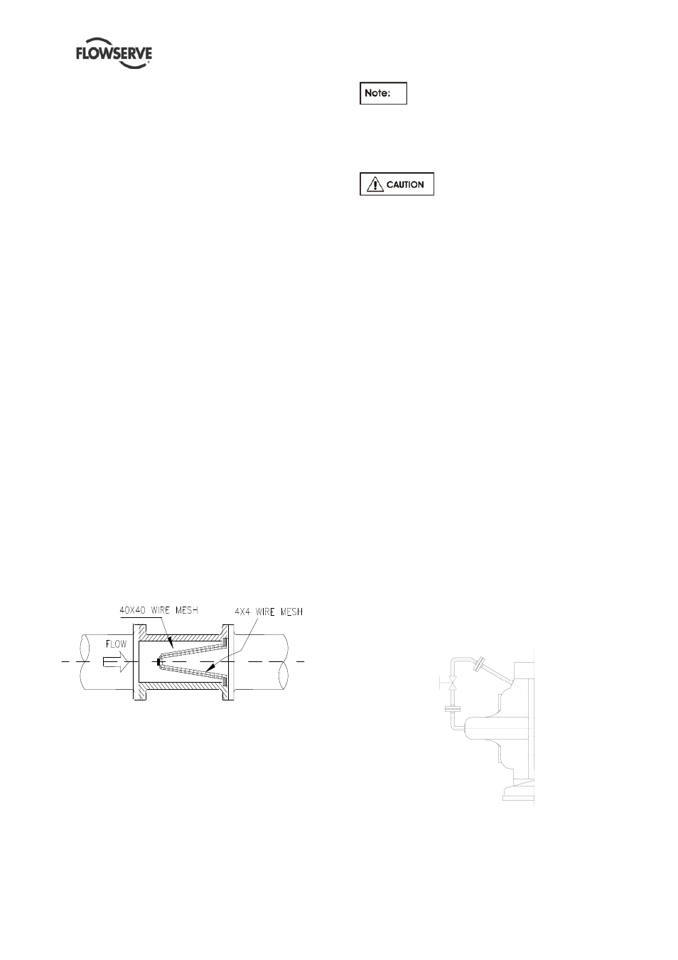
4.4.2.1 Suction Strainer
It is recommended that a temporary strainer be
placed in the suction pipe to prevent lodging of
foreign material in the pump. A pipe spool of
sufficient size should be provided with gauge taps
to accommodate the suction strainer.
The strainer should be installed as close to the
pump as possible.
The open area of the strainer should have a
minimum of a 3 to 4 ratio to the area of the pump
inlet.
The strainer is usually conical and should be made
of 40x40 mesh screen (corresponding to an
aperture lower than 0.4 mm - 0.0157 in.), backed
up by 4x4 mesh hardware cloth (corresponding to
an aperture lower than 4.7 mm - 0.185 in).
Pressure gauges should be installed on both sides
of the strainer, so the pressure drop across the
strainer can be measured when the unit is
operated.
Figure
4.8 Typical temporary suction strainer
Pressure gauges should be installed on both sides
of the screen so that the pressure drop across the
screen can be measured.
When the unit is being started, the gauges on each
side of the screen should be carefully watched. An
increase in the differential pressure between the
two gauges indicates that the screen is becoming
clogged with dirt and scale. At this point, the pump
should be shut down, and the screen cleaned
and/or replaced.
A spool piece should be installed in
suction line so that the suction strainer may be
installed and removed with a pressure gauge
between the strainer and pump.
4.4.2.2 Bypass Line
Operation at low flows results in
pump horsepower heating the liquid. A bypass
may be required to prevent vaporization and
subsequent pump damage. Refer to local
FLOWSERVE branch to determine if a bypass
is required. Mechanical damage may result
from continuous operation at flows less than
specified.
4.4.3 Discharge piping
a) Install a check valve and a gate valve in the
discharge pipe of the pump. When the pump
is stopped, the check valve will protect the
pump against excessive pressure and will
prevent the pump from running backward. The
check valve should be installed between the
gate valve and the pump nozzle in order to
permit its inspection. Never throttle pump on
suction side and never place a valve directly
on the pump inlet nozzle.
b) Pipework reducers should have a maximum
total angle of divergence of 15 degrees.
4.4.4 Drains and Vents
Pipe pump casing drains and vent to a convenient
disposal point.
4.4.5.1 Pumps fitted with gland seal
When suction pressure is below ambient pressure
it is necessary to feed the gland packing with liquid
to provide lubrication and prevent the ingress of
air. This is normally achieved with a supply from
the pump discharge volute to the stuffing box.
A control valve is fitted in the line to enable the
pressure to the gland to be controlled.
If the pumped liquid is dirty and cannot be used for
sealing, a separate clean compatible liquid supply
to the gland at 1 bar (15 psi) above suction
pressure is recommended.