Flowserve LPNV Worthington User Manual
Page 38
LPNV USER INSTRUCTIONS ENGLISH 87900031 – 06/14
Page 38 of 48
6.9.2 Rotor Assembly
To reassemble the pump, reverse the dismantling
procedure previously described.
The torque table value in Chapter 6.6 provides a
guide for properly assembling the equipment.
Proceed as follows:
a) Place split locating ring in relevant shaft groove.
b) Install shaft sleeve against locating ring.
c) Place impeller key in relevant shaft key-way.
d) Install impeller against shaft sleeve.
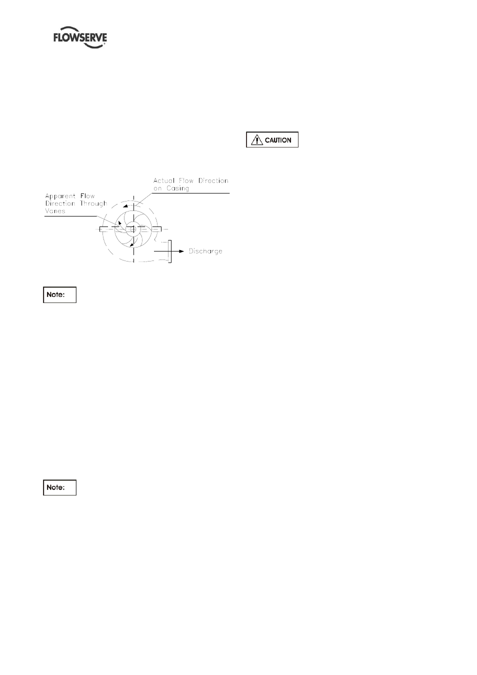
Direction of impeller rotation
Figure 6.5
Take care to mount the impeller so that
the vane tips point away from the apparent flow
direction (See figure 6.5).
e) Install impeller locking nut. Screw nut until it butt
against the impeller hub.
f) Locate casing rings on impeller. Secure bottom
casing ring to the impeller with tape or wire.
g) Place in position stuffing box throat bushing.
6.9.3 Pump
completion
a) Sling and suspend rotating element vertically
against the stationary casing half, taking care that
the impeller is centered as closely as possible in
its volute and throttling bushing, shaft guide
bushing and casing rings are inserted in their
respective seats.
Bottom bearing bushing is pinned to
end cover. Bolt (snug up) end cover to stationary
casing half.
b)
Install removable casing half against the
stationary one. Close up pump, applying the
torque values recommended on in Chapter 6.6,
tightening first of all the central studs and then
proceeding towards the periphery and outer
ends.
c) Fix end cover to the casing.
d) Lower pump rotor until rotor weight is borne by
the casing.
e) Stuffing box assembly
-
Gland packing: Insert inner two rings of packing,
then lantern ring halves and finally 2 or 3 more
rings of packing. Loosely fit the gland and
connect flush line.
-
Mechanical seal: Fasten seal covers complete
with O-ring and connect flush line. Connect any
auxiliary piping.
At this tag don’t lock mechanical
seal sleeve to pump shaft and don’t remove
setting tab or spacer.
f) Assemble and install complete thrust bearing
assembly. Adjust bearing housing until dowel pins
can be driven into place on bearing bracket.
g) Centralize impeller in its volute, acting on
adjusting nut. Lift rotor against upper stop in the
casing and measure total axial clearance. Lower
rotor an amount equal to half of above
measurement.
h) Screw adjusting nut lock screws.
i) Lock mechanical seal sleeve (if fitted) to pump
shaft and remove setting tab or spacer.
j) Install coupling key and pump half coupling (if
fitted), coupling nut and coupling nut set screws.
k) Turn rotor by hand to ensure there are no rubs or
binding.
6.9.4 Unit
reinstallation
a) Install motor stand on soleplate and set electric
motor as described under Section 6.7.1.
b)
Check driver/driven shafts alignment and
assemble flexible coupling.
c) Replace all auxiliary piping, instrumentation and
pipe plugs.
d) Install oiler and fill thrust bearing housing to
correct oil level (refer to Section 5.1.1
“Lubrication”).
e) Install coupling guards.
f) Refer to section 5.6 “Operation” for starting
procedure.