5 piping – Flowserve MEN User Manual
Page 13
MEN
USER INSTRUCTIONS ENGLISH 71576288 – 11-09
Page 13 of 36
®
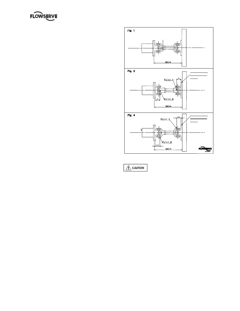
4.4.2 Drive shaft assembly
The battery must be disconnected. The distance
between the end of the pump shaft and the engine
flywheel must be 380 mm
±
5 mm. The pump and
diesel engine must be aligned once the cardan link
is fitted between the pump shaft and the engine
flywheel.
The maximum axial misalignment allowed between
the pump and the engine flywheel shaft is 9 mm
±
4.5 mm on each side of the shaft used as a
reference for alignment (see fig.1).
All that is required to align the pump and engine
drive shafts correctly is a measuring tape or ruler
graded in millimeters.
Alignment is checked as indicated below:
1) See fig.2
Place the marking A/B engraved on the surface of
the cardan link flange at the top in the vertical
position (12 o’clock).
Measure the distance X between the flange and the
outside of the cardan shaft (point A). This distance
must be 76 mm
±
3 mm.
With the cardan in the same position as above,
measure the distance Y between the flange and the
outside of the cardan shaft (point B). This distance
must be equal to the distance X
±
1mm.
2) See fig.3
Turn the cardan 90° and place markings C/D
engraved on the surface of the cardan link flange at
the top in the vertical position.
Measure the distance X1 between the plate and
outside of the cardan shaft (point A). This distance
must be 78 mm
±
1 mm.
With the cardan in the same position as above,
measure the distance Y1 between the flange and
outside of the cardan shaft (point B). This distance
must be equal to the distance X1
±
1mm.
Alignment is achieved by moving and/or shimming
one or both of the elements.
4.5 Piping
Protective covers are fitted to the
pipe connections to prevent foreign bodies entering
during transportation and installation. Ensure that
these covers are removed from the pump before
connecting any pipes.
4.5.1 Suction and discharge piping
The dimensions of the pipes do not directly depend
on suction and discharge diameters of the pump:
a) First, choose a flow speed < 2 m/s at suction, and
about 3 m/s at discharge.
b) Take into account the available NPSH, which
must be superior to the required NPSH of the pump.
Never use pump as a support for piping. Do not
mount expansion joints in such a way that their
force, due to internal pressure, may act on the pump
flange.
Maximum forces and moments allowed on the pump
flanges vary with the pump size and type. These
external strains may cause misalignment, hot
bearings, worn couplings, vibrations and the
possible failure of the pump casing.
Motor side
Motor side
Motor side
Pump side
Pump side
Pump side
F
ly
w
h
e
e
l
F
ly
w
h
e
e
l
F
ly
w
h
e
e
l
Reference A/B
on drive shaft
flange
Reference C/D
on drive shaft
flange
Motor side
Motor side
Motor side
Pump side
Pump side
Pump side
F
ly
w
h
e
e
l
F
ly
w
h
e
e
l
F
ly
w
h
e
e
l
Reference A/B
on drive shaft
flange
Reference C/D
on drive shaft
flange
The maximum misalignment
allowed between the pump and
engine axis is 9 mm
±
4.5 mm