4 running the pump – Flowserve MEN User Manual
Page 24
MEN
USER INSTRUCTIONS ENGLISH 71576288 – 11-09
Page 24 of 36
®
5.3.2.2 Putting into service:
After completion of these checks and tests, the plant
may be put into service:
- Turn the selector switch to the "AUTO" position
- Valves of the cooling circuit locked in the open
position and the discharge valve of the pump
positioned.
- Check all fill levels.
- Power-on displayed with light indicator.
5.3.2.3 Plant maintenance and servicing:
Once a week, check the voltage and electrolyte level
of each battery; the water level of the internal
cooling circuit, the engine oil fuel tank levels.
Respect all instructions given in the pump and
engine manuals, as well as the regulations R1 given
in appendix IV of the APSAD.
Do not run the pump with the outlet valve closed for
a period longer than 10 minutes.
If NO pressure, or LOW pressure, STOP the pump.
Refer to fault finding chart for fault diagnosis.
The pump must never run at a capacity of less than
40 % of that at the best efficiency for a longer
period.
Never remove a plug when the pump is
running.
The pump should run smoothly and without
abnormal vibration for a diesel engine.
5.4 Running the pump
Never remove the exhaust heat screens.
The combustion engine may attain a temperature of
80 °C during operation and up to 450 °C at the
exhaust pipe. Specific instructions must be sign-
posted to inform all persons present of the risk of
burns.
Inspections by the operator:
* The pressure gauge on the switching enclosure
indicates the oil pressure in the diesel engine block:
if the pressure gauge indicates a pressure lower
than that designated by the red arrow on the dial,
the engine must be stopped immediately by
switching the selector switch to stop and moving the
stop lever on the diesel engine.
* The thermometer on the switching enclosure
indicates the diesel engine cooling water
temperature: if the thermometer indicates a
temperature higher than that designated by the red
arrow on the dial, the engine must be stopped
immediately using the same procedure as indicated
above.
The engine may only be restarted by an employee
qualified by FLOWSERVE.
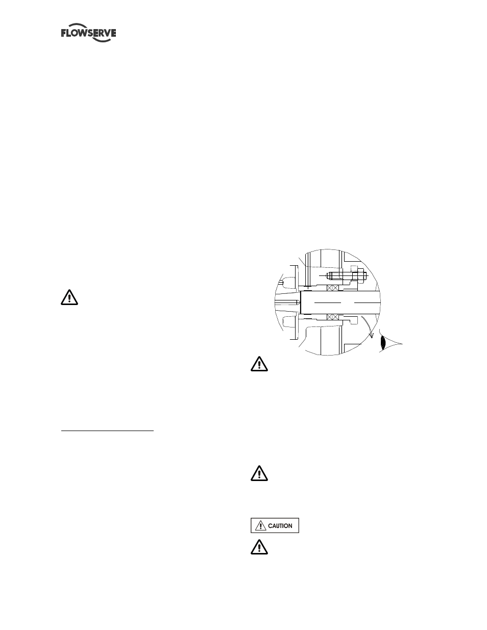
5.4.1 Pump fitted with a stuffing box
If the pump has a packed gland there must be some
leakage from the gland. Gland nuts should initially
be finger-tight only. Leakage should take place soon
after the stuffing box is pressurized. If no leakage
takes place the packing will begin to overheat. If
overheating takes place the pump should be
stopped and allowed to cool before being re-started.
When the pump is re-started it should be checked to
ensure leakage is taking place at the packed gland.
The pump should be run for ten minutes with steady
leakage and the gland nuts tightened by 10 degrees
at a time until leakage is reduced a steady thin
continuous stream is acceptable. The temperature of
the gland should be checked after each round of
tightening. If the temperature starts to climb rapidly
then back off the gland nuts at standstill until the
temperature drops down. Wait for the temperature to
stabilize before tightening again. The leakage must
not be reduced below a rate of 60 drops per minute.
Bedding in of the packing may take several hours.
Shield grids being removed during installation
of the gland packing, it must be ensured that they
are replaced as soon as this operation is completed.
SAFETY INSTRUCTIONS WHEN THE PUMP IS
RUNNING.
If hot or freezing components of the machine can
present a danger to operators, they must be
shielded to avoid accidental contact. If a 100 %
protection is not possible, the machine access must
be confined to the maintenance staff only.
If the temperature is greater than 80 °C, a
warning plate must be clearly placed on the pump.
Check that the gland lightly tightens the packing
rings.
Risk of seal ring overheating.
After examination of the packing gland, DO
NOT FORGETS TO REFIT THE BEARING
PROTECTION SCREENS.