8 batteries, 9 switching on, 10 charge starter batteries – Flowserve MEN User Manual
Page 17: 11 final shaft alignment check
MEN
USER INSTRUCTIONS ENGLISH 71576288 – 11-09
Page 17 of 36
®
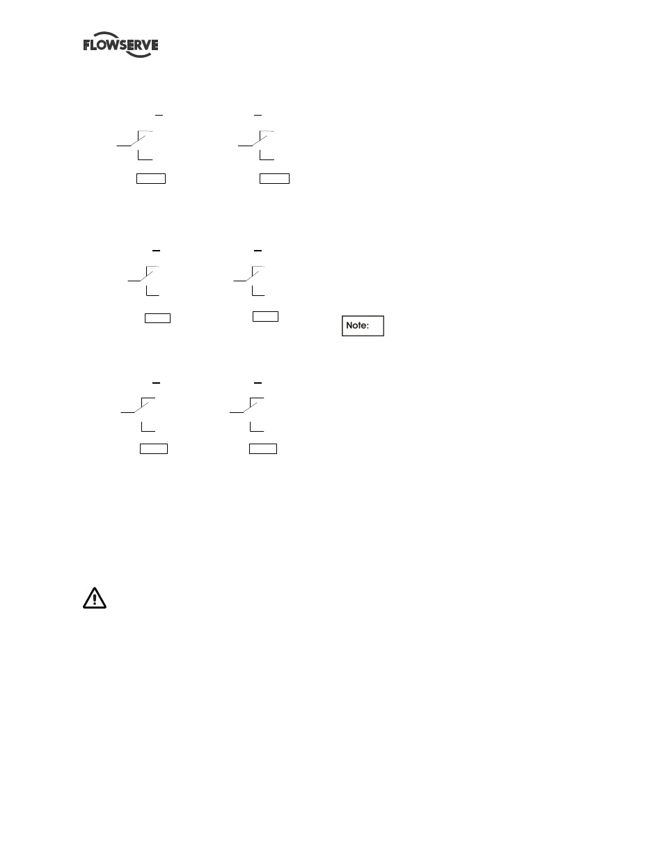
Connection of general fault data on terminals n° 30
and n° 31
A
B
8 9
9 2
9 0
9 3
9 1
9 4
3 0
3 1
Information connection Failure risk on n° 28 and n°
29 terminals
A
B
8 3
8 6
8 4
8 7
8 5
8 8
2 8
2 9
Information connection
No start-up on n° 37 and n° 38 terminals
A
B
1 1 0
1 1 3
1 1 1
1 1 4
1 1 2
1 1 5
3 7
3 8
4.8 Batteries
The lead-cell batteries are supplied "dry charged".
Switch off the "AUTO-STOP-MANUAL" key switches
on the front panel of the switching enclosure.
Electrolyte is supplied by FLOWSERVE separately
in 1.7-litre plastic containers.
Electrolyte is a sulphuric acid-based liquid.
Appropriate protective clothing must be worn during
handling. Avoid any contact with skin or clothing. In
case of splashing, rinse thoroughly with running
water (in case of contact with eyes, consult a doctor
immediately).
Prepare the batteries 1 week before commissioning.
Fill the batteries with electrolyte up to the maximum
fill level indicated with a line in the top section of the
battery.
The cables must not be exposed to oil, diesel or acid
splashing and should be run accordingly.
Check that the batteries are connected to the right
poles and securely fastened (++ and --).
4.9 Switching on
The pump unit is supplied with the starter solenoid
disconnected to avoid accidental start-up of the
diesel engine during commissioning preparation
work.
Reconnection may only be carried out by an
employee qualified by FLOWSERVE, after
examination before start-up.
The unit may only be switched on by an employee
qualified by FLOWSERVE.
- Place the operating mode selector switch in the
"Off" position.
- Close the switching terminals 5 and 6.
- Close fuse holders F1 to F4 and the circuit-breaker
DD1.
A siren sounds when these electrical
circuits are closed, press the "Siren off" and "cancel
fault" push-buttons.
- Close the main circuit-breaker.
- The following indicators white/power on,
green/electronics on, green/ charge batteries 1 or 2
and orange/non-auto, must be on.
4.10 Charge starter batteries
Both batteries are connected independently and
alternatively to a self-regulated battery charger.
A possible charge fault is signaled by the "Charger 1
or charger 2 fault" indicator on the front panel of the
enclosure, with activation of a local audible alarm
signal and tripping of the general fault contact.
Each charger supplies the corresponding battery
with a variable charge current in accordance with the
battery charge level.
- Keep a bottle of distilled water available for topping
up of electrolyte level.
The battery voltage selector switch enables
monitoring of the battery voltage with charger supply
interrupted.
4.11 Final shaft alignment check
Check the alignment pump-motor according to the
procedure § 4.4.2.
Rectify if necessary by adjusting the motor only!
- If it is planned, connect piping (hydraulic,
pneumatic, sealing system)
- Control seal and the working of auxiliary piping.