6 electrical connections, 7 connection – Flowserve MEN User Manual
Page 16
MEN
USER INSTRUCTIONS ENGLISH 71576288 – 11-09
Page 16 of 36
®
4.5.3 Final checks
a) Check the tightening of anchor bolts. Tighten
them if necessary.
b) Check that protective covers on suction and
discharge flanges are removed.
c) Check that holes of piping flanges are parallel and
correspond to those of the pump.
d) Tighten suction and discharge flanges.
e) Check the alignment pump-motor according to the
procedure § 4.4.2.
Rectify if necessary by adjusting the motor only!
f)
If it is planned, connect piping (hydraulic,
pneumatic, sealing system).
g) Control seal and the working of auxiliary piping.
4.6 Electrical connections
Electrical connections must be made
by a qualified Electrician in accordance with relevant
local national and international regulations. This
includes any grounding.
It is important to be aware of the EUROPEAN
DIRECTIVE on electromagnetic compatibility when
wiring up and installing equipment on site. Attention
must be paid to ensure that the techniques used during
wiring/installation do not increase electromagnetic
emissions or decrease the electromagnetic immunity of
the equipment, wiring or any connected devices. If in
doubt, contact Flowserve for advice.
The installation comprises all appropriate safety
devices such as magnetic overload, current
overload, earth leakage relays, etc.... Ensure the
power supply corresponds to the power rating given
for the switching enclosure, i.e.: 5 kVA (220 V).
An electrical protection device shall be fitted.
Carry out the ground connections according to the
current local regulations.
4.7 Connection
Proceed with electrical connections to the terminals
in accordance with instructions 71576402 01-06.
Connect the switching enclosure to the mains power
supply and check the supply voltage on terminals 39
and 40 (220 V single-phase).
Connect the start-up signal wires:
Double terminal n° 11: pressure switch N° 1. B-
contacts
of these pressure switches must be
potential free.
Double terminal n° 12: pressure switch N° 2.
Actual recommendations require the start-
up signal contact to be open-started. All delivered
units meet this requirement.
Information regarding the cabinet:
Sensor connection at recovery tank level on #15
double terminal. The contact will be opened in case
of lack of water in the main tank and potential free.
Opening the circuit controlling the
primer tank starts the engine.
Options:
Sensor connection at the bottom of the primer tank
on #16 double terminal. The contact will be opened
in case of lack of water at the bottom of the primer
tank and is potential free.
Sluice blade or ventilation damper connection on
#43 and 44 double terminal (220 V servomotor).
Sluice blade opening limit connection on #15 double
terminal. The contact will be closed when ventilation
sluice blades are open and potential free.
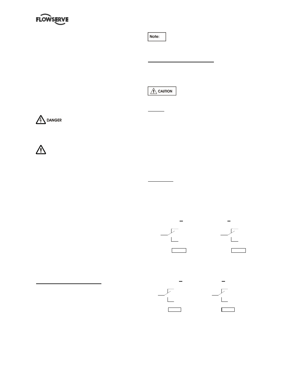
Alarm report:
All alarm reports are proposed on 2 changeover
contacts (A and B) by 2 triple terminals.
Connection of running data motor on terminals
n° 35 and n° 36
A
B
1 0 4
1 0 7
1 0 5
1 0 8
1 0 6
1 0 9
3 5
3 6
Manual connection of switching fault data on
terminals n° 33 and n° 34
A
B
9 8
1 0 1
9 9
1 0 2
1 0 0
1 0 3
3 3
3 4