Flowserve BP User Manual
Page 16
BP USER INSTRUCTIONS ENGLISH 85392725 10-09 (E)
Page 16 of 44
flowserve.com
horizontally as required. In some cases where the
alignment cannot be achieved it will be necessary to
move the pump before recommencing the above
procedure.
Proceed as follows.
a) Disconnect the coupling halves by removing the
coupling bolts. Then remove the coupling spacer.
b) Check the distance between the coupling halves (or
pump shafts and driver shaft) against the
dimensions shown on the outline drawing supplied.
For any necessary adjustment, move the driver.
Use the adjusting bolts of base plate at the driver
side, if provided
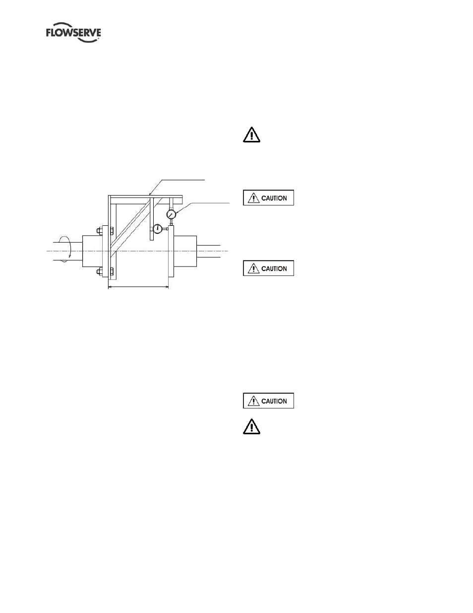
Fig. 4-4
c) Mount the dial indicators, as shown on Fig. 4-4,
ensuring the bracket is rigid and long enough to
extend across the space between the coupling
hubs, on the driver side coupling.
d) Rest the dial indicator’ probe on the outer
diameter of the pump side coupling as shown on
Fig. 4-4. Rotate the driver shaft by hand and take
reading of dial indicator at every quarter turn to
check parallel alignment.
e) Next, after rotating the pump shaft by 180°turn,
rotate the driver shaft and take reading of dial
indicator at every quarter turn again, and take the
average of 1st and 2nd readings.
f) Move the driver by using the adjusting bolts or
shim under the driver feet until parallel readings
are within 0.05 mm (0.002 in).
g) Rest the dial indicator probe, on the coupling face
as shown on Fig. 4-4 for angular alignment.
Rotate the driver shaft and take reading of dial
indicator in accordance with the same method as
the parallel alignment.
h) Adjust the driver side until both parallel and
angular readings are within 0.05 mm.
i) After the coupling has been accurately aligned,
install the coupling spacer and tighten the
coupling bolts.
Permissible misalignment limits at working temperature:
Parallel alignment
- 0.05 mm (0.002 in.) TIR maximum
Angular alignment
- 0.05 mm (0.002 in.) per 305 mm (12 in) TIR
maximum
When checking parallel alignment, the total indicator
read-out (TIR) shown is twice the value of the actual
shaft displacement.
Complete piping as below and see sections 4.7,
Final shaft alignment check
up to and including section
5, Commissioning, start-up, operation and shutdown,
before connecting driver and checking actual rotation.
4.6 Piping
Protective covers are fitted to the pipe
connections to prevent foreign bodies entering during
transportation and installation. Ensure that these
covers are removed from the pump before connecting
any pipes.
4.6.1 Suction and discharge pipework
Never use pump as a support for piping.
Maximum forces and moments allowed on the pump
flanges vary with the pump size and type. To
minimize these forces and moments that may, if
excessive, cause misalignment, hot bearings, worn
couplings, vibration and the possible failure of the
pump casing, the following points should be strictly
followed:
Prevent excessive external pipe load
Never draw piping into place by applying force to
pump flange connections
Do not mount expansion joints so that their force, due
to internal pressure, acts on the pump flange
Ensure piping and fittings are flushed
before use.
Ensure piping for hazardous liquids is arranged
to allow pump flushing before removal of the pump.
Take into account the available NPSH which must be
higher than the required NPSH of the pump.
In order to minimize friction losses and hydraulic
noise in the pipework it is good practice to choose
pipework that is one or two sizes larger than the
pump suction and discharge. Typically main
pipework velocities should not exceed 2 m/s (6 ft/sec)
suction and 3 m/s (9 ft/sec) on the discharge.
Jig
Dial Gauge
Drive side
Measured by vernier calliper
“L”