4 recommended spares, 5 tools required – Flowserve BP User Manual
Page 26
BP USER INSTRUCTIONS ENGLISH 85392725 10-09 (E)
Page 26 of 44
flowserve.com
the original design specification (modification or use
of a non-standard part) will invalidate the pump’s
safety certification.
6.3.2 Storage of spares
Spares should be stored in a clean dry area away
from vibration. Inspection and re-treatment of
metallic surfaces (if necessary) with preservative is
recommended at 6 monthly intervals.
6.4 Recommended
spares
The list below outlines the minimum requirement for
spare parts to be retained onsite.
The minimum number of spare parts which should be
carried in stock at the site of the installation, should
be determined based on the severity of the condition
of service, the extent to which repairs can be carried
out in the field and number of units installed
No.
NAME OF PARTS
REQUIRED REPLACEMENT
1
Diffuser rings and
Stage piece rings
When he original clearance has
doubled.
Or
When there is a significant drop
of pump performance.
2 Gaskets
Every
overhaul
3 “O”rings
Every
overhaul
4
Shaft sleeve and
Breakdown bushing
When he original clearance has
doubled.
Or
When leakage from shaft
sealing becomes unacceptable.
5 Bearing
Every
two
years.
Or
When increase of noise or
vibration becomes unacceptable
Or
When abnormal rubbing noise is
detected at the bearing.
6
Balancing drum and
Balancing ring
When the clearance between
the drum and ring has become
1.5 times larger than the original
clearance.
6.5 Tools
required
A typical range of tools that will be required to
maintain these pumps is listed below.
Readily available in standard tool kits, and dependent
on pump size:
Open ended spanners (wrenches) to suit up to
M36 bolt or nut head
Socket spanners (wrenches), to suit up to M36
bolt or nut head
Range of screwdrivers
Soft
mallet
More specialized equipment:
Bearing
pullers
Bearing induction heater
Dial test indicator
C-spanner (wrench) - for removing shaft nut.(If
difficulties in sourcing are encountered, consult
Flowserve.)
Coupling grip/shaft spanner
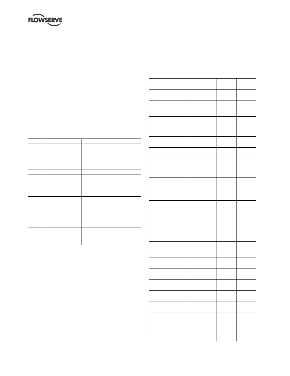
All additional special tools are described in the
Special Tools List and are supplied with your pump.
No Name
Remark
Journal
Bearing
Ball
Bearing
1
Extension
Sleeve
Assembly of
Rotor
●
●
2
Lifting Lug
Diffuser of
Rotor
Element
●
●
3
Lifting Lug
Shaft of
Rotor
Element
●
●
4 Shaft
Lug
Shaft
●
●
5
Face Spanner
Wrench
Coupling Nut
●
●
6 Belt
Wrench Turning
●
●
7
Lock Nut
Wrench
Thrust Collar
Nut
●
8 Hooker
Thrust Collar
Lock Nut
●
9 Hooker
Bearing
Nut
○
1
●
10 Eye
Bolt
Last Stage
Diffuser
●
●
11
Eye Bolt
Stage Piece
●
●
12
Eye Bolt
Diffuser
○
2
○
2
13
Lifting Jig
Diffuser
○
3
○
3
14 Pulling
Jig
Disassembly
of Discharge
Head
●
●
15 Fixing
Jig
Diffuser of
Rotor
Element
●
●
16 Coupling
Assembly of
Rotor
●
●
17 Plate
Assembly of
Rotor
●
●
18
Center Bolt &
Nut
Assembly of
Rotor
●
●
19 Bolt
Assembly of
Rotor
●
●
20 Eye
Bolt
Balancing
Drum
●
●
21 Eye
Bolt
Bearing
Housing
●
●
22 Sleeve
Spirolox
Ring
○
4
○
4
23
Tool Box
●
●