Flowserve BP User Manual
Page 35
BP USER INSTRUCTIONS ENGLISH 85392725 10-09 (E)
Page 35 of 44
flowserve.com
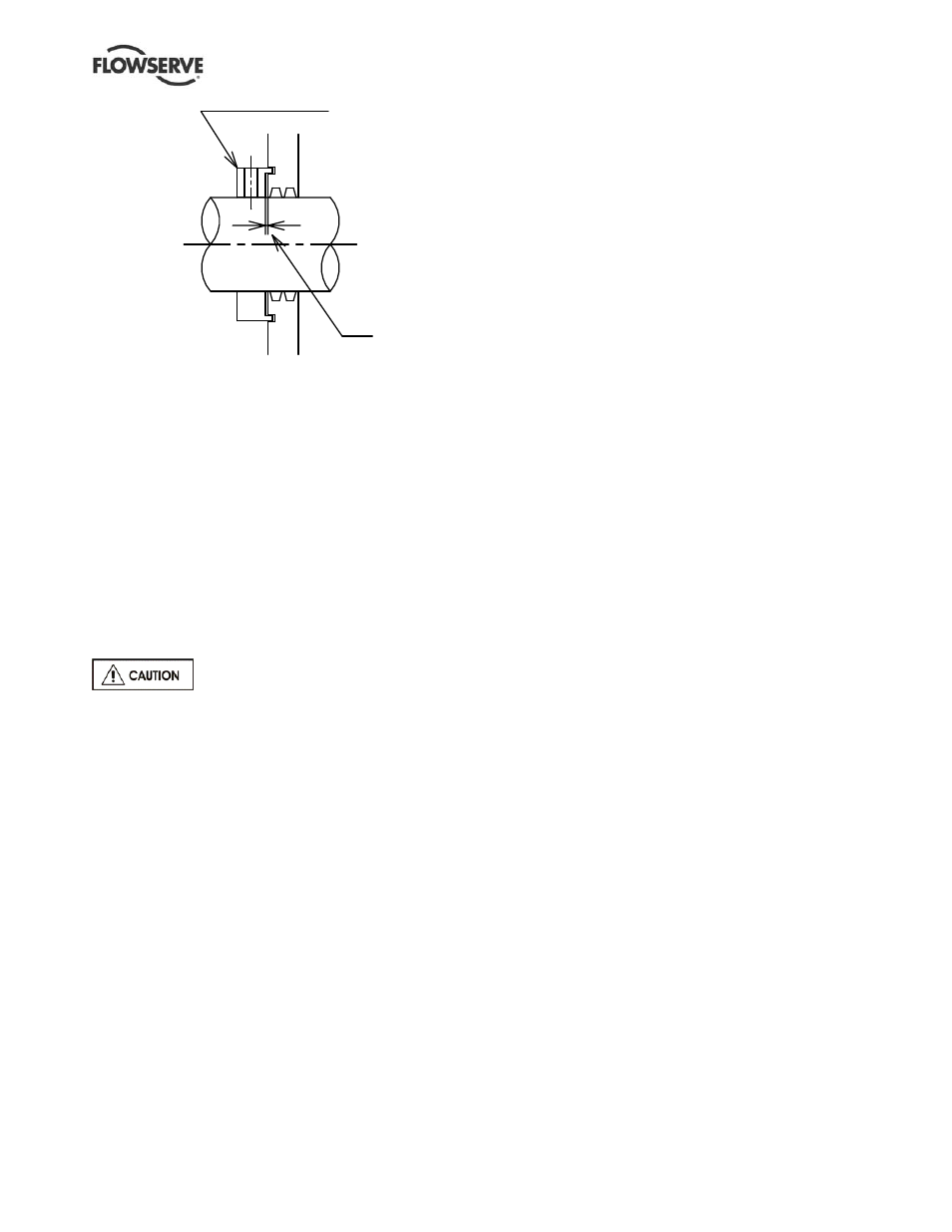
Fig. 6-1
6.10.9 Assemble of Thrust Bearing and Set
Thrust Bearing Axial End Play
a) Place shims and spacers [6196, 3645] into the
lower half of thrust bearing housing for the same
thickness of which were removed at the
disassembly.
b) Apply heat to the thrust collar [3610] up to
maximum 93°C, if it is shrink fitted, then
assemble to shaft together with key [6700].
Assemble thrust collar nut [3712.1] and bearing
nut [3712.3]. After cooled down the thrust collar,
tighten again the thrust collar nut [3712.1] and
lock nut [3712.2].
c) Push the rotor toward the coupling end as far as
it will go.
IF THE IMPELLER REACHES THE
CHANNEL RING, IT WILL BE STOPPED, DO NOT
FORCE ROTOR
d) Place a dial indicator at the end of thrust bearing
housing with the indicator tip resting on the end
of the shaft. Zero the indicator.
e) Push the rotor for both ends as far as it will go
and record the total axial movement of the rotor.
f) Pour a small amount of oil on thrust collar and
thrust shoes. Install lower half of inboard thrust
bearing assembly [3032].
g) Push rotor towards coupling end of pump as far
as it will go (tight against inboard thrust bearing
assembly). Check and see by the dial gage that
the rotor is positioned at the centre of the total
axial movement of the rotor. This can be
obtained by adjusting the thickness of shims
[6196, 3645].
h) After the rotor position is confirmed, install lower
half of outboard thrust bearing assembly [3032].
i) Assemble shims [6196, 3645], then assemble
bearing cover [3266].
j) Install a dial indicator on radial end bearing
housing so the indicator contracts the end of the
shaft. Push the rotor outboard (towards thrust
bearing) and set indicator at zero. Push rotor
inboard. Indicator should read the value as thrust
bearing total end play.
See “Important Clearances and Movement Table”
in section 10.4 Technical Data Sheet. Add or
remove shims [6196, 3645] to obtain proper
endplay. Now to centralize rotor axially and to
set thrust bearing axial end play is completed.
k) Disassemble the bearing cover [3266].
l) Assemble the upper half of journal bearing
[3020], upper half of inboard and outboard thrust
bearing [3032].
m) Ensure bearing housing upper and lower half
parting flange surfaces are clean and free of old
jointing. Coat with a thin layer of liquid packing.
n) Assemble upper half of thrust bearing housing to
bearing lower half and to the stuffing box. Install
dowel pins and tighten cap screws to the
specified torque value.
o) Assemble bearing cover [3266] to thrust bearing
housing with the gasket [4590] and seal ring
[4305] on the bearing cover and tighten bolts.
Oil pump is mounted on thrust end of shaft
a) Assemble bearing cover [3266] to thrust bearing
housing with the gasket [4590] and seal ring
[4305] on the bearing cover and tighten bolts.
b) Fit the key [6700] into thrust end of shaft and
Lovejoy coupling.
c) Assemble oil pump to bearing cover [3266] with
gasket [4590] on the bearing cover and tighten
bolts
Phase disk is fitted on thrust end of shaft
a) Assemble bearing cover [3266] to thrust bearing
housing with the gasket [4590] and seal ring
[4305] on the bearing cover and tighten bolts.
b) Slide the phase disk along the shaft with key
[6700] against the shoulder of shaft and fasten
thrust collar nut [3712.1] by using lock nut wrench
(Tool List No.8). And then install bearing washer
and fasten bearing nut [3712.3] by using the
hooker (Tool List No.8). In order to prevent the
bearing nut from loosing, insert the lip of the
bearing washer into the shaft keyway and bend a
tongue of the washer into the slot of the bearing
nut.
c) Assemble bearing end cover [3266.2] to bearing
cover [3266.1] with gasket [4590] on the bearing
end cover and tighten bolts
6.10.10 Assemble of Radial Bearing
a) Assemble the upper half of journal bearing
[3020].
Oil Baffle
Clearance
1mm
Deflector Set
Position