Flowserve VCT User Manual
Page 15
USER INSTRUCTIONS APM, APMA and APH MX0301 - 07/03
Page 15 of 32
®
NOTE
As outer column (1350) is being removed from
upper shaft (2130), the blocking under exposed
portion of upper shaft will have to be removed and
reinstalled under exposed portion of upper shaft.
e) Install sling along upper shaft (2130) and rig to
an overhead hoist. Remove the bolting
between the gib key and shaft coupling (7238).
Remove split ring (7415) from groove in pump
end shaft (2110). Slide shaft coupling up on
upper shaft until the shaft coupling key in upper
shaft is exposed. Remove both gib key and
shaft coupling key in upper/pump end shaft
(2110). Using the overhead hoist, lift and place
upper shaft on horses and block to prevent
rolling and dropping. Remove shaft coupling
(7238) from lower end of upper shaft.
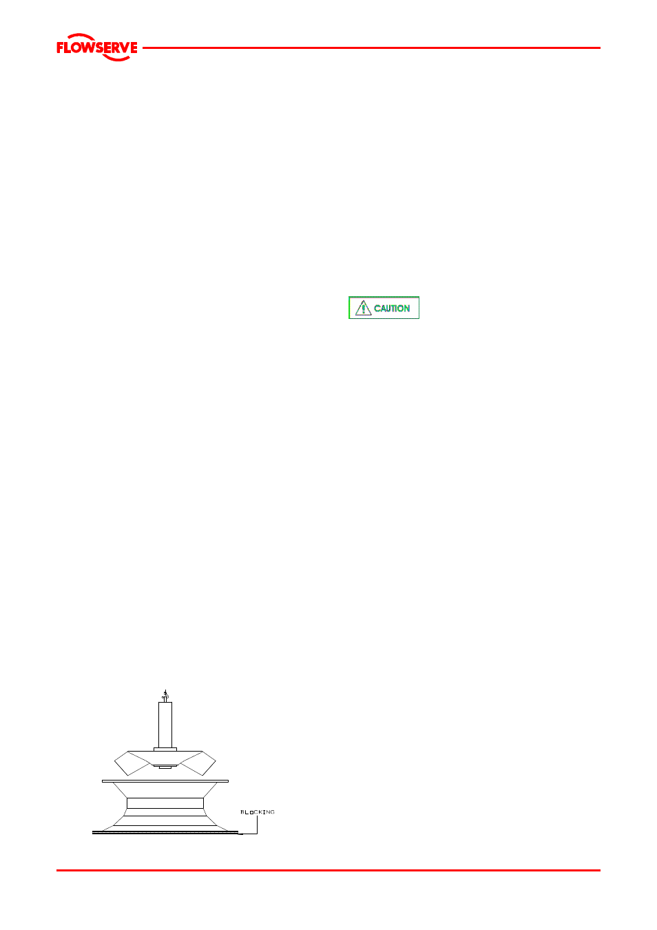
f) Install a sling in exposed upper flange of casing
(1170) and rig to overhead hoist. Install a sling
around suction head (1130) and rig to auxiliary
hoist. Using both hoists, lift the pump assembly
from blocking and carefully maneuver into a
vertical position until assembly is suspended
vertically from the rigging attached to the
eyebolts in casing (1170) upper flange. At not
time should the pump rotated or supported on
the suction head.
g) Remove the casing to suction head bolting
(6579). Using the rigging attached to casing
(1170) upper flange. Lift and remove casing off
over upper end of pump end shaft. Remove
“gasket eliminator” (See point 10.3) from
mating surfaces of casing and suction head
(1130).
NOTE
E
Take care when removing the casing (1170) so as
not to damage bearings (3312)
h) Install eyebolts and slings (not provided) into
upper end of the pump end shaft (2110) and rig
to overhead hoist, Remove pump end shaft
and impeller (2262) as a unit from the suction
head (1130).
i)
Remove the four socket head caps crews (6579 )
with lockwasher from the split lock collar (2531).
Block up the impeller (2262). Place a block of wood
over the top of the pump shaft (2110) and tap until
lock collar is completely clear of the impeller.
Remove the lock collar (2110) and withdraw the
pump shaft , with key (6710) from the impeller,
Place pump shaft on horses and block to prevent
rolling.
6.8.1 Multistage pumps
Described procedure is applicable for pumps with
two or more stages which will be disassembly and
assembly at same way, see figure 8.1.3 page 22
6.9 Examination of parts
Used parts must be inspected
before assembly to ensure the pump will
subsequently run properly. It is recommended
replace all gaskets, “O” rings, bearings and wear
rings during overhaul.
In particular, fault diagnosis is essential to enhance
pump and plant reliability.
1. Wire brush and clean all pump parts. Inspect
parts for wearing, corrosion, and erosion. Inspect
the impeller (2262) and casing (1170) for cracks.
2. Indicate each section of shaft on rollers or V-
blocks for runout.
A. Indicate each section of shaft on “V” blocks or
rollers for total indicated runout (TIR). The shaft
shall be supported by two “V” blocks (rollers) near
the ends of the shaft at the bearing and/or coupling
areas of approximately the same diameter. The TIR
of the rollers (“V blocks) shall not exceed .0005
inches per foot, with a maximum variation of
0.005”. The shaft journals or journals sleeves must
be round to within .001 inch at the support areas on
the “V” blocks or rollers.
B. Total indicator readings should be taken at every
bearing and coupling area and/or every 12 inches
between long bearing spans. Record distances
from end of shaft to each TIR measurement. TIR
measurements are to be taken every 90 degrees
around the shaft.
C. Maximum allowable TIR is .001 inch X total
length of shaft in feet. Shaft that exceed the limit
can be straightened by either cold straightening or
heat straightening. Refer to Flowserve Engineered
Pump Division for heat straightening procedure.