Flowserve VCT User Manual
Page 16
USER INSTRUCTIONS APM, APMA and APH MX0301 - 07/03
Page 16 of 32
®
3. Journal sleeves (3420).
Inspect journal sleeves. If journal sleeves are worn,
they can be removed and sliding sleeves from
shafts. Install new journal sleeve onto shaft and
locate sleeve on its key.
4. Bearings (3320)
A. Removal
Remove setscrews from bearings. Bearing can be
removed by pressing the old bearing out of its
respective fit in the stuffing box extension (4110)
and casing (1170). If this is not practical, bearing
must be machined until disappear it
B. Assembly
Chill rubber bearing and fit into place or press
bronze bearing into its fit.
If graphite bearings are supplied, they can be
installed using a constant hydraulic press in dry,
but, it is recommended that bushings should be
dipped in water solvent or kerosene for easier
installation.
Chill carbon bearing using nitrogen or refrigerator is
a good option too.
CAUTION
WHEN INSTALLING THE “CUTLESS RUBBER
BEARING” (3300- 3320) DO NOT CHILL TO
LESS THAT 0°F. AS THE RUBBER PORTION OF
THE BEARING WILL DETACH FROM ITS
RESPECTIVE METAL BACKING.
Install new setscrews in bearings and apply “loctite”
(screw lock grade) to the threads.
NOTE
If used holes for bearing setscrews cannot be
located when installing the bearings, then new
holes will have to be drilling to spot the bearings to
ensure securing to the bearing in their proper
location with setscrew.
5.-Renew “O” rings (4610) and packing (4120)
during reassembly procedure.
6.10 Assembly
To assemble the pump consult the sectional
drawings, see section 8, Parts list and drawings.
Ensure threads, gasket and O-ring mating faces
are clean. Apply thread sealant to thread fittings.
Threaded fittings torque should be periodically
checked to assure that it is at the recommended
value and be sure fittings are not loose.
6.10.1 Wear rings
a) Impeller rings (when fitted) should be slipped
onto the impeller and pressed down to the
shoulder. (Do NOT use a steel hammer to
knock them into position).
b) Drill and tap 3 holes approximately 120° apart
into the diametral mating faces of the ring and
impeller and insert set screws. (The existing
tapped holes from the removed impeller ring
cannot be re-used).
c) Case wear rings must be fitted onto casing (Do
NOT use a steel hammer to knock them into
position) and locate set screws approximately
120° apart (The existing tapped holes from the
removed set screws cannot be re-used).
d) Check the running clearance between impeller
and casing ring against value indicated in
attachment in these User Instructions.
6.10.2 Reassembly
a) Place pump shaft (2110) on horses and block to
prevent rolling. Install impeller key (6710) in
machined groove of pump shaft (2110). Install
impeller (2262) on shaft.
b) Install split lock collar (2531), plus four cap
screw / tabwashers. Tighten the cap screws to
a final torque and bend the tab of the washer.
c) Install the eyebolt (not provided) into coupling
end pump shaft (2110) and rig to an overhead
hoist. Raise pump shaft with impeller intact, to
a vertical position.
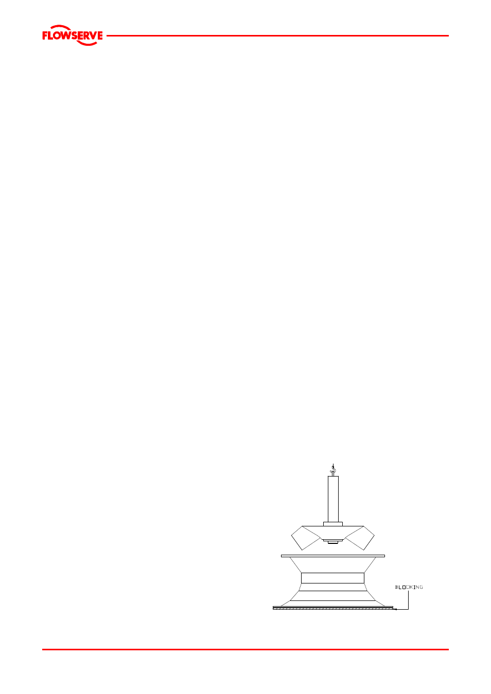
d) Be sure suction head (1130) assembly is
properly supported, in a vertical position,
blocking on the floor. Carefully place pump
shaft with impeller, into suction head (1130)
until impeller vanes are resting against inner
wall of suction head.