Flowserve Valtek Mark 200 User Manual
Page 14
Mark 200 Control Valve FCD VLENIM0200– 12/12
14
DIN Disassembly and Reassembly
10.1 Disassembling the Body
To disassemble the valve body, refer to Figure 8 or 9 then proceed
as follows:
WARNING: Depressurize line to atmospheric pressure and
drain all fluids before working on the valve. Failure to do so
can cause serious injury.
1. Fully retract the plug until the stem clamp indicator points to the
open position.
2. Remove the actuator bolting and lift the actuator out of the
linear thrust unit.
CAUTION: Heavy actuators may require a hoist.
3. Unlock the hex nut (5.7) counter clockwise.
4. Unlock the linear thrust unit - lock nut counter clockwise.
5. Unscrew the complete linear thrust unit counter clockwise.
6. Measure the distance from stroke indicator disk (5.9) to the stem
(2.4) top edge. Make a note of the dimension, you will need it for
reassembling.
7. Remove the stroke indicator disk (5.9) and unscrew the hex nut (5.7).
8. Unscrew hex nuts (5.3) and remove the extension sleeves (1.5).
9. Unscrew hex nuts (3.6).
10. Remove gland flange (3.4).
11. Turn the special tool (ring nut, see Table 10.3) on the stem and put in
place slowly.
WARNING: Danger exists in removing the bonnet and plug with
piston ring balancing. The balanced ring may stick to the plug
and fall during disassembly, causing possible serious injury
and damage to the valve or nearby equipment.
12. Remove flat gasket (1.2).
13. Insert special tool (change seat tool, see Table 10.3) in the body and
remove using a suitable torque wrench (see table 5).
14. Remove screwed seat (2.1) and profile ring (2.5).
15. Remove plug - unit (2.2, 2.3, 2.4) from the bonnet.
16. Remove packing (3.3) and bottom ring (3.2) with special tool
(packing driver tool, see Table 10.3).
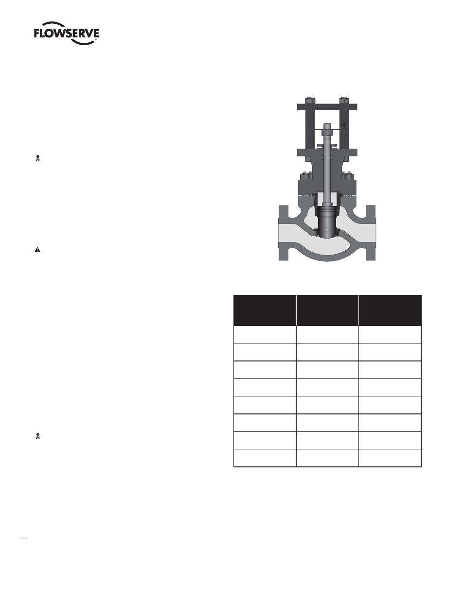
Figure 9 – DIN Mark 200 Cutaway Drawing
DN
PN160
Moment [Nm]
Torque [ft lb]
PN250
Moment [Nm]
Torque [ft lb]
50
190
140
420
310
80
590
435
1290
950
100
880
650
1930
1420
150
2200
1620
4800
3540
200
3700
2730
8150
6000
250
6100
4500
13400
10000
300
8900
6550
19600
14400
400
12000
8850
26400
19400
Table 5: DIN Mark 200 Required Torque for Screwed-in Seat Ring