2 reassembling the body – Flowserve Valtek Mark 200 User Manual
Page 15
15
Mark 200 Control Valve FCD VLENIM0200– 12/12
flowserve.com
10.2 Reassembling the Body
To reassemble the valve body, refer to Figure 8 or 9 then proceed as follows:
1. Install new profile ring (2.5) and screwed seat (2.1).
NOTE: Clean and inspect all sealing surfaces, threads and remove
damaged parts. Allways use new gaskets whenever the valve is
disassembled.
2. Insert special tool (change seat tool, see Table 10.3) in the body and
turn using a suitable torque wrench (see Table 5).
3. Lower plug unit (2.2, 2.3, 2.4) in the body and put it in the
screwed seat.
NOTE: Check the stem surface for damage. A damaged stem must
be replaced.
4. Install new flat gasket (1.2).
5. Lower the bonnet (3.1) onto the plug unit and body carefully.
NOTE: Take great care to avoid scoring the stem.
6. Fit the extension sleeves (1.5) onto the stud bolts (1.3) and fingertighten
the nuts (1.4).
7. Tighten the nuts (1.4) in four steps (crosswise with 30%, 60%, 100%
and all round 100%) according to the pattern (Figure 10).
NOTE: Check the movement of the plug by lifting (10 mm) between the
steps. If it is hard to move, loosen the nuts and start again.
8. Lower the bottom ring (3.2) and the new packing (3.3).
NOTE: Instal one ring after the other. To do this, use a tamper and push
in each ring individually, carefully and complete. When inserting the
other rings, rotate them each by 180° from their overlapping points.
9. Lubricate the thread and all bearing surfaces (underside of the nuts)
with a suitable, approved lubricant.
10. Place the gland flange (3.4) back on and tighten the nuts (3.6),
alternating evenly in accordance with the instructions from the packing
manufacturer.
NOTE: Tightening unevenly can cause the packing gland follower to jam,
which can result in stem damage.
11. Screw the hex nut (5.7) onto the stem (2.2) and replace the stroke
indicator disk (5.9). Recall the distance between top edge of stem and
replace it.
12. Lower the linear thrust unit. Lock nut onto the stroke indicator disk and
screw the complete linear thrust unit onto the stem clockwise.
13. Screw on the linear thrust unit. Lock nut onto the linear thrust
unit clockwise and secure it. Do the same with the hex nut (5.7).
NOTE: The stroke indicator disk should be shown in the open position on
the stroke indicator plate.
14. Replace the multi turn actuator.
15. After replacing the valve in the pipe, perform three full strokes and
check the thigtening torque of the nuts (3.6). Retighten the nuts as
necessary.
16. Log the maintenance interval and the work performed.
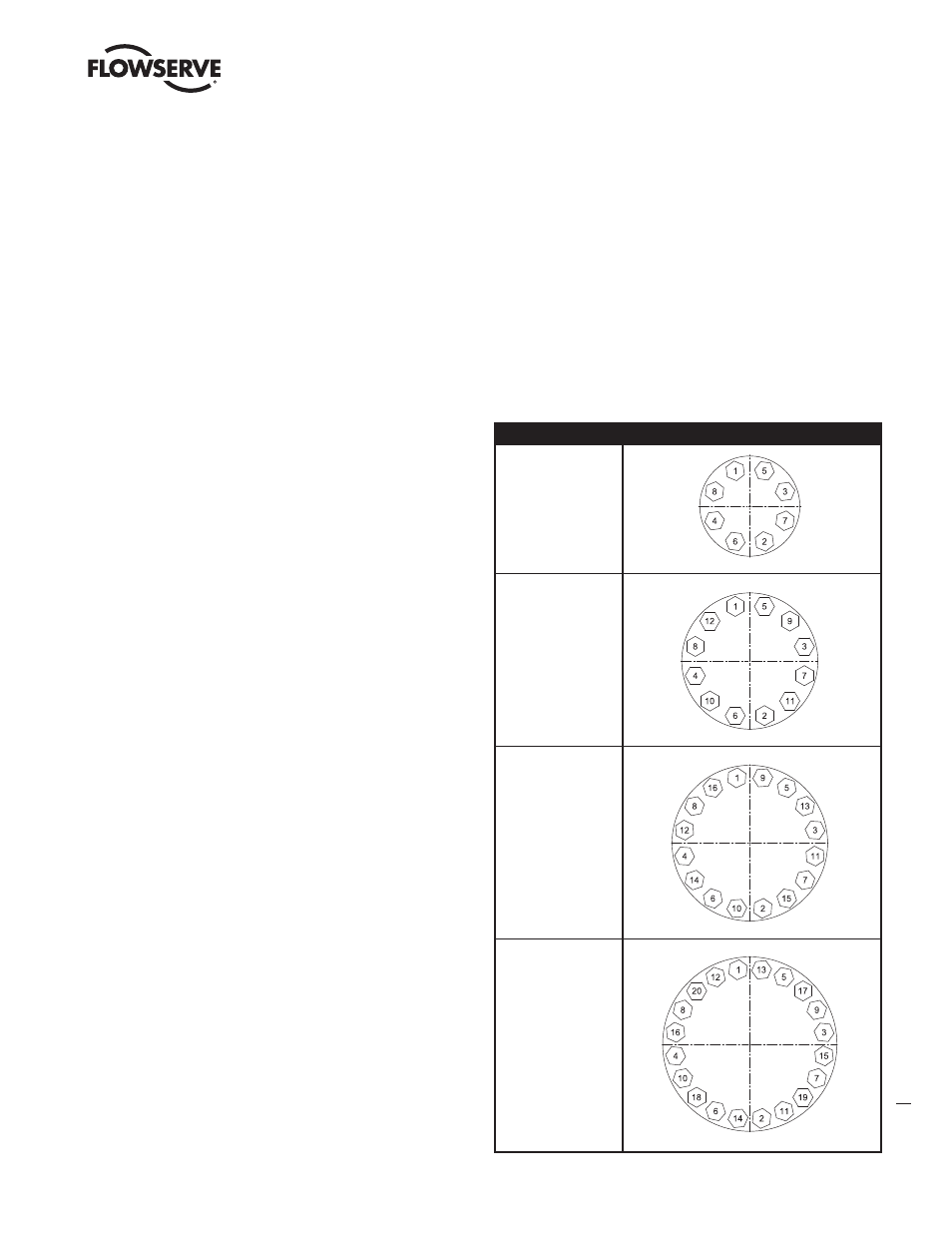
Figure 10 – Bolt Patterns
Bolts
Cross Bolt Tightening Pattern
8 bolts
45° apart
12 bolts
30° apart
16 bolts
22,5° apart
20 bolts
18° apart