1 disassembling the body, Asme disassembly and reassembly – Flowserve Valtek Mark 200 User Manual
Page 7
7
Mark 200 Control Valve FCD VLENIM0200– 12/12
fl owserve.com
ASME Disassembly and Reassembly
6.1 Disassembling the Body
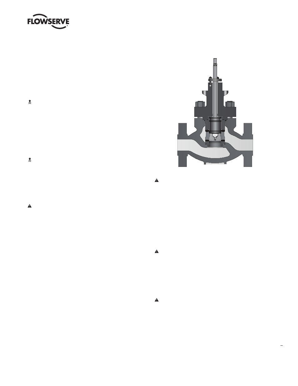
To disassemble the valve body, refer to Figure 3 or 4 then proceed
as follows:
WARNING: Depressurize line to atmospheric pressure and
drain all fl uids before working on the valve. Failure to do so
can cause serious injury.
1. Fully retract the plug until the stem clamp indicator points to the open
position.
2. Remove the bonnet fl ange bolting and lift the actuator, bonnet and plug
out of the valve body.
WARNING: Danger exists in removing the actuator, bonnet and
plug, especially if PTFE plug seals are used. The sleeve may
stick to the plug and fall during disassembly, causing possible
serious injury and damage to the valve or nearby equipment.
If sleeve is observed sticking to the plug, steps 3–5 should be
consulted.
CAUTION: Heavy actuators may require a hoist. Lift the actuator
with the yoke legs using a lifting strap and a hoist. Great care
should be taken to lift the actuator and plug straight out of the
body to avoid damage to the plug and seat.
3. If the sleeve is observed sticking to the plug during removal, fully extend
the plug by applying air above the piston, allowing the sleeve to remain
in the body and the bonnet to rise above the body.
4. In the gap between the top of the sleeve and the bottom of the bonnet,
place wooden blocking of equal thickness in at least three places. The
wooden blocks must not extend in far enough that they interfere with
plug movement. The plug must be allowed to stroke up to the bonnet.
5. By applying air below the piston, retract the plug until the plug head is
freed from the sleeve. Once the plug is free from the sleeve, remove the
plug and bonnet assembly from the body.
6. Lift the sleeve out of the valve body using lifting points on the top of the
sleeve.
7. Remove cage, seat ring and gaskets from the valve body.
8. Remove the plug seals from the plug head.
9. Check to see the seating surfaces on both the seat ring and plug are
free of damage to ensure tight shutoff. Make sure the gasket surfaces
on the seat ring, bonnet and body are clean and undamaged. Inspect the
pressure balanced sleeve for scratches or other damage.
10. Loosen the stem clamp and gland fl ange. Remove the yoke bolts.
CAUTION: If a rubber bellows is attached to the gland fl ange,
the gland fl ange must be removed prior to removing the
actuator.
11. Turn the actuator off the plug and bonnet without allowing the plug to
rotate within the bonnet. Pull the plug carefully through the packing box.
Inspect the plug stem for damage or scoring.
NOTE: With air-to-close, fail-open valves, it may be necessary to apply
a small amount of air to the top of the actuator to move the plug away
from the bonnet. Otherwise, plug galling may occur.
CAUTION: To avoid scoring guides and plug stem, follow the
above procedure exactly.
12. If the seat surfaces need remachining, both surfaces on plug and seat
ring must be reworked. The seat angle on the plug is 36 degrees and
the seat ring is 33 degrees. Lapping is not necessary if proper assembly
procedures are followed.
CAUTION: If remachining, protect the stem while turning.
Ensure concentricity of the seat surface with the plug stem (or
outside diameter of the seat ring, if machining the seat).
13. To replace packing or change the packing box confi guration, push out
packing, spacer and guides with a dowel slightly larger than the plug
stem from underneath the bonnet.
Figure 4 – ASME Mark 200 Cutaway Drawing