Flowserve Valtek Mark 200 User Manual
Page 9
9
Mark 200 Control Valve FCD VLENIM0200– 12/12
flowserve.com
4. Lower the plug into the body and sleeve. Care should be taken with the
plug seals to avoid scoring or galling the sealing surface while fitting
them into the sleeve bore. With metal multi-seals and carbon triple
seals, use a ring compressor on the rings. A suitably sized screw-type
hose clamp will also serve to compress the rings for reassembly.
5. Install sleeve gasket by centering on sleeve.
6. Lower the bonnet onto the plug and body, taking great care to avoid
scoring the plug stem.
7. Once the bonnet is resting squarely in the valve body, finger-tighten the
bonnet flange bolting.
8. Reinstall the packing and guides referring to the appropriate packing
installation manual and reinstalling new packing exactly as shown.
Make sure at least 1⁄8” (3 mm) is left at the top of packing box for the
top guide to enter. Different spacer lengths permit a wide variety of
packing configurations, such as twin seal and vacuum-pressure packing
WARNING: Valves with extended bonnets must not have
lower packing installed. Instead, lower packing rings should
be installed with the upper set. Lower packing installed in
extended bonnets will diminish the integrity of the packing
assembly.
NOTE: Graphite guide liners should be replaced each time the valve
packing is replaced. Do not rebuild the valve without new graphite liners
in the guides.
9. Replace and tighten the packing gland and bolting. Refer to the packing
installation manual for specific details on maintaining the style of
packing supplied. Make sure gland flange is level after 3 nuts are
tightened.
10. Turn actuator back onto the body assembly, without turning the plug
inside the bonnet. Leave a 3⁄32” to 1⁄8” (2 mm to 3 mm) gap between
the mating surfaces of the bonnet and yoke. Tighten yoke bolting to
close this gap. Firmly tighten the yoke bolting.
11. Using the actuator, seat the plug two or three times to center the seat
ring using pressure on the top of the actuator.
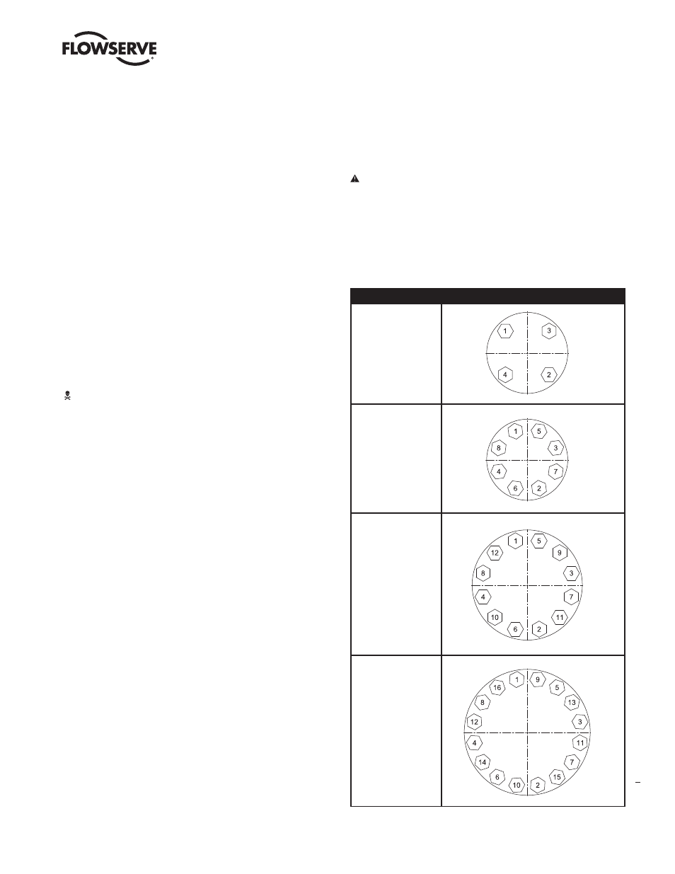
12. Tighten the body bolting, following the bolting sequence outlined in
Figure 7. Use a minimum of four steps to reach the suggested bolt
torque values shown in Table 2. Never exceed more than 30% of the
suggested bolt torque value in a single step.
13. Slowly stroke the plug up and down to check the alignment of the plug
with the sleeve.
CAUTION: If binding or sticking is observed, discontinue
stroking the valve and reassemble using the above steps.
Failure to do so could cause serious valve damage. Contact
your Flowserve representative if binding cannot be resolved.
14. Perform a Quick Check as described in section 4.1.
Figure 7 – Bolt Patterns
Bolts
Cross Bolt Tightening Pattern
4 bolts
90° apart
8 bolts
45° apart
12 bolts
30° apart
16 bolts
22,5° apart