Wiring, Connect level switch nrgs 15-1, Tools – Flowserve NRGS15-1 User Manual
Page 19: Connect level switch nrgs 15-1 tools
19
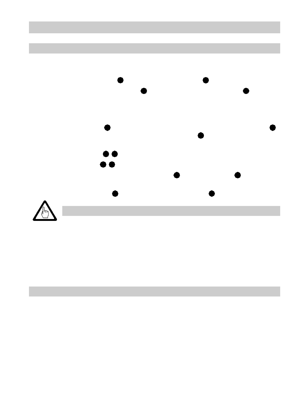
Wiring
Connect level switch NRG S 15-1
Use multi-core flexible control cable with a min. conductor size of 0.75 mm² as mains and
control cables.
1.
Undo the housing screws
and remove the housing lid
.
2.
Unplug the two-pole terminal strip
and the twelve-pole terminal strip
from the
electronics insert.
3.
Strip off approx. 40 mm of cable insulation coating and remove approx. 5 mm of con-
ductor end insulation.
4.
Loosen cable glands
and run the mains cables through the lower cable gland
and the control cables through the upper cable glands
.
5.
Connect mains and control cables according to the wiring diagram (inside of housing
lid) to terminal strips
,
.
6.
Plug terminal strips
,
to electronics insert.
7.
Seal cable entries by tightenting cable glands
. Use sealing plugs
for cable
glands that are not used.
8.
Replace the housing lid
and tighten the housing screws
firmly.
Tools
■
Screwdriver for cross recess head screws, size 1 and 2
■
Screwdriver for slotted screws, size 2.5, completely insulated according to VDE 0680
G
F
J
H
I
I
I
H
J
H
J
I
I
F
G
Attention
The following relocations of cables with basic insulation are not permissi-
ble: Mains and control cables in low voltage areas
Provide level switch and control circuit with a slow-blow 2.5A fuse.
Provide connected contactors with RC combinations according to manu-
facturer's specification to ensure interference suppression.
Note that the sealing plugs are not scope of the supply.