Collector board, Field terminations – Flowserve 1000 Series Digitial Positioner User Manual
Page 10
FCD AXAIM0064-00 (AUTO-64) 08/04
Page: 10 of 16
© 2004, Flowserve Corporation, Printed in U.S.A.
Logix Series 1000 Digital Positioner
Installation, Operation and Maintenance Instructions
Flowserve Corporation
1350 N. Mountain Springs Parkway
1978 Foreman Dr.
Flow Control Division
Springville, Utah 84663-3004
Cookville, TN 38501
www.flowserve.com
Phone: 801 489 2233
Phone: 931 432 4021
© TriCom, Inc., 2004, All Rights Reserved.
Collector Board
The collector board assembly provides a central routing
for all electronic connections in the positioner, linking the
pressure modulator coil, hall effect sensor and field inputs
to the main electronics. The collector board assembly also
serves as a mounting for the pressure sensors used on
the advanced board.
Removing Collector Board (Figure 19)
1. Make sure valve is bypassed or in a safe condition.
2. Disconnect the power and air supply to the unit.
3. Remove the main cover and disconnect the wiring to
the collector board. Each cable has its own unique
connector to prevent mistakes in reconnecting.
4. Remove the three No. 8-32 screws holding the
collector board to the housing.
5. Remove the collector board.
Replacing/Upgrading Collector Board (Logix 1X1X)
1. For the advanced collector board, check that pressure
sensors are in place on back of collector board. For the
standard model (Logix 1X0X), make sure the adapter
block is securely fastened to the collector board.
2. Set collector board assembly in place.
3. Insert three No. 8-32 screws through collector boards
into the threaded holes on sensor shelf and standoff.
4. Tighten all three screws.
5. Connect the main ribbon from electronics tray.
6. Reconnect wiring to the collector board.
Field Terminations
The field terminations board provides a connection point
inside the explosion proof housing for all hookups to
positioner. While the board is not likely to experience a
failure, it can easily be replaced to upgrade positioner.
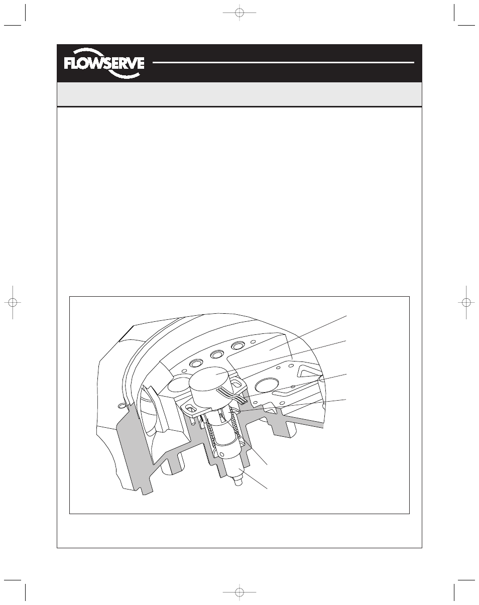
Figure 15: Stem Position Sensor Orientation
Housing
Stem Position
Sensor
Sensor Cable
Feedback Shaft
Stem Position
Sensor Dot
Bearing
(AXAIM0096-00) Logix 1000 IOM 8/6/04 3:34 PM Page 10