Detailed sequence of positioner operations, Mounting the positioner – Flowserve 1000 Series Digitial Positioner User Manual
Page 3
Logix Series 1000 Digital Positioner
Installation, Operation and Maintenance Instructions
Flowserve Corporation
1350 N. Mountain Springs Parkway
1978 Foreman Dr.
Flow Control Division
Springville, Utah 84663-3004
Cookville, TN 38501
www.flowserve.com
Phone: 801 489 2233
Phone: 931 432 4021
© TriCom, Inc., 2004, All Rights Reserved.
FCD AXAIM0064-00 (AUTO-64) 08/04
Page: 3 of 16
© 2004, Flowserve Corporation, Printed in U.S.A.
Detailed Sequence of Positioner Operations
An increase in the command signal causes the modulator
pressure to increase, pushing the spool assembly upward
from its equilibrium position. This opens the spool valve
ports, supplying air to Output 1 and exhausting air from
Output 2 (Figure 1). This causes the actuator shaft to rotate.
The shaft rotation is transmitted back to the positioner
through the stem position feedback linkage, changing
proportionally to the valve stem position. The actuator
shaft continues to rotate until the stem position signal
of the sensor increases sufficiently to counter the signal
being sent to the control algorithm. At this point, the
spool is at its equilibrium position as the pressures in
the cylinder stabilize and the air flow to the actuator
decreases. The computer will then make small null
adjustments to fine-tune the desired position and
compensate for changes in dynamic loading. A decrease
in the command signal reverses the described actions.
Mounting the Positioner
CAUTION: Positioner shaft is spring-loaded and features
mechanical stops at each end of stroke. Failure to
follow these procedures carefully may result in severe
damage to positioner. Read through entire procedure
before starting.
1. Attach positioner mounting bracket to actuator using
fasteners supplied with bracket (Figure 2). Tighten
bolts finger-tight only at this time.
2. Install coupler (if required – coupler is not required
for NAMUR mounting) on actuator shaft, making sure
it is centered.
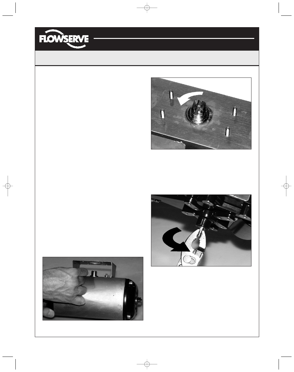
3. Stroke the actuator to determine direction of rotation
as shown in Figure 3. Pay specific attention to the slot
that will engage positioner shaft.
4. Carefully grasp positioner shaft with pliers as shown in
Figure 4. Turn shaft to determine direction of rotation.
5. Making sure positioner shaft rotation matches actuator
shaft rotation, place positioner on mounting bracket
(Figure 5). Make sure shafts engage. Do not insert
fasteners into positioner at this time.
6. Double-check actuator and positioner rotation. Hold
positioner against bracket with fingertips as shown in
Figure 6.
Figure 2: Positioner Mounting Bracket
Figure 3: Actuator Shaft
Figure 4: Turn Positioner Shaft
(AXAIM0096-00) Logix 1000 IOM 8/6/04 3:34 PM Page 3