Tubing positioner to actuator, Wiring and grounding guidelines – Flowserve 1000 Series Digitial Positioner User Manual
Page 4
Logix Series 1000 Digital Positioner
Installation, Operation and Maintenance Instructions
Flowserve Corporation
1350 N. Mountain Springs Parkway
1978 Foreman Dr.
Flow Control Division
Springville, Utah 84663-3004
Cookville, TN 38501
www.flowserve.com
Phone: 801 489 2233
Phone: 931 432 4021
© TriCom, Inc., 2004, All Rights Reserved.
FCD AXAIM0064-00 (AUTO-64) 08/04
Page: 4 of 16
© 2004, Flowserve Corporation, Printed in U.S.A.
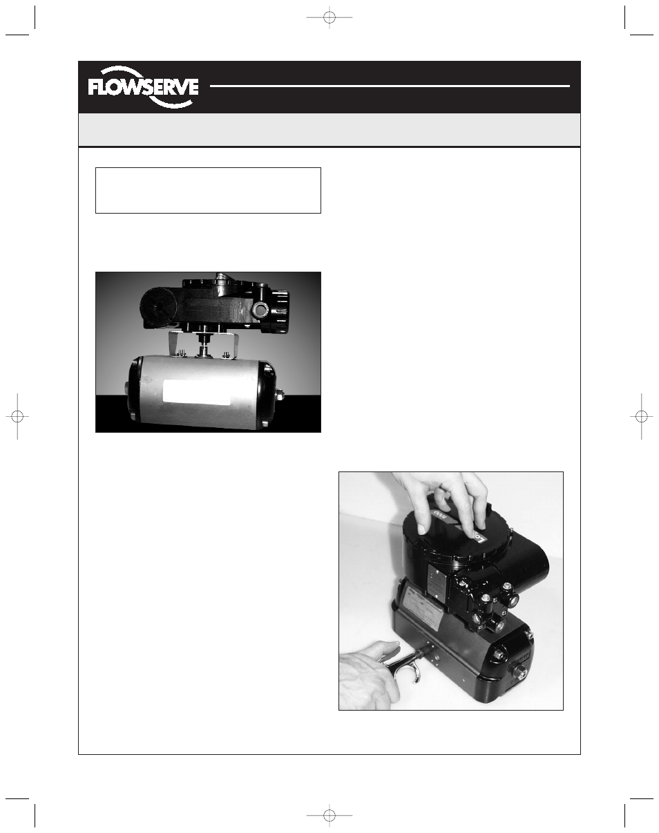
WARNING: Keep away from positioner sides, as
positioner will suddenly rotate on bracket if not
properly aligned and cause injury.
Slowly rotate the actuator. If the positioner shaft is
properly aligned, the shaft will rotate freely. If not, the
mechanical stops will grab, causing the positioner body
to rotate on bracket.
7. If the shaft is not properly aligned, repeat steps 3-6.
Otherwise, attach positioner to bracket with fasteners
included with bracket. Tighten bolts finger-tight only at
this time.
8. Stroke actuator/positioner several times to align shafts.
Tighten all fasteners.
Tubing Positioner to Actuator
Proper tubing orientation is critical for the positioner to
function correctly and have the proper failure mode. Referring
to Figure 1, note that for air-to-open valves, the Output 1 port
of the positioner manifold, is tubed to the ‘open’ side of the
actuator. The Output 2 port of the positioner manifold is tubed
to the ‘closed’ side of the actuator. For air-to-close valves the
above configuration is reversed.
Wiring and Grounding Guidelines
Input Cable Shielding (Figure 8)
The input loop current signal to the Logix 1200 positioner
should be in shielded cable. The shields must be tied to a
ground at only one end of the cable to provide a place for
environmental electrical noise to be removed from the cable.
In general, shield wire should be connected at the source.
Grounding Screw
The green grounding screw that is located inside the
termination cap should be used to provide the unit with an
adequate and reliable earth ground reference. This ground
should be tied to the same ground as the electrical
conduit. Additionally, the electrical conduit should be
earth grounded at both ends of its run.
NOTE: The green grounding screw must not be used to
terminate signal shield wires.
Compliance Voltage (Figure 7)
Output compliance voltage refers to the voltage limit that
can be provided by the current source. A current loop
system consists of the current source, wiring resistance,
barrier resistance (if present), and the Logix Series 1200
impedance. The Logix 1200 positioner requires that the
current loop system allow for a 12 VDC drop across the
positioner at maximum loop current. The 12 VDC drop
across the Logix 1200 positioner terminals is generated
by the positioner from the 4-20 mA loop current input.
CAUTION: Never connect a voltage source directly
across the positioner terminals. This could cause
permanent circuit board damage.
Figure 5: Positioner on Mounting Bracket
Figure 6: Check Positioner Shaft Alignment
(AXAIM0096-00) Logix 1000 IOM 8/6/04 3:34 PM Page 4