Checking or setting internal regulator pressure – Flowserve 1000 Series Digitial Positioner User Manual
Page 13
FCD AXAIM0064-00 (AUTO-64) 08/04
Page: 13 of 16
© 2004, Flowserve Corporation, Printed in U.S.A.
Logix Series 1000 Digital Positioner
Installation, Operation and Maintenance Instructions
Flowserve Corporation
1350 N. Mountain Springs Parkway
1978 Foreman Dr.
Flow Control Division
Springville, Utah 84663-3004
Cookville, TN 38501
www.flowserve.com
Phone: 801 489 2233
Phone: 931 432 4021
© TriCom, Inc., 2004, All Rights Reserved.
Checking or Setting Internal Regulator
Pressure
1. Disconnect the air supply from the positioner.
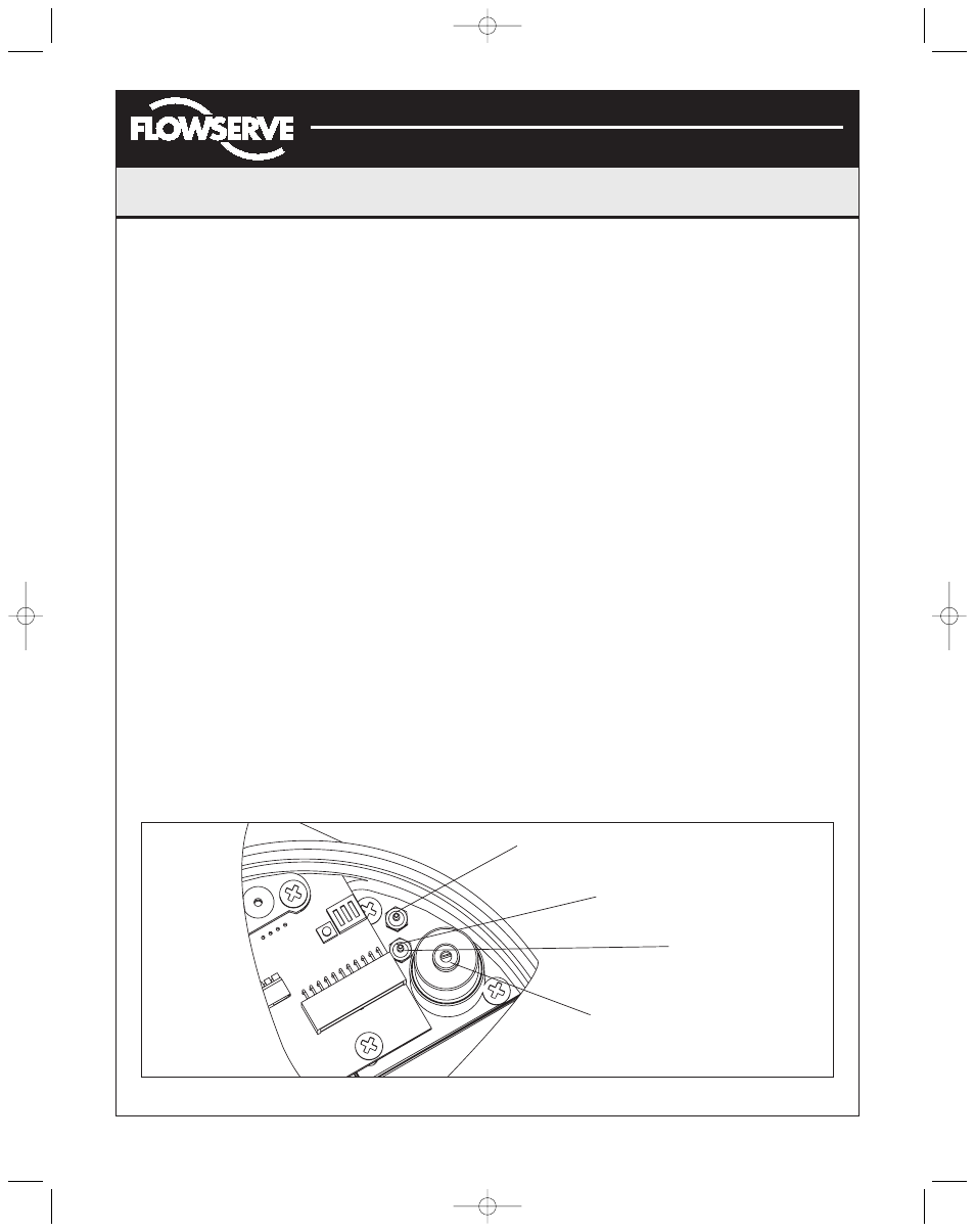
2. Remove the main cover. The regulator pressure set
port is factory plugged with a No. 10-32 hex plug
(Figure 18). Replace hex plug with a No. 10-32 x .06
barb fitting.
3. Using a 0 to 30 pressure gauge attached to some
.06 flexible tubing, push the .06 tubing onto the barb
fitting shown in Figure 18.
4. Reconnect the air supply to the positioner and read the
internal regulator pressure on the 0 to 30 gauge (the
internal regulator should be set to 22.0 psi). Adjust the
regulator pressure by turning the set screw with a
small flat screwdriver.
5. Once the regulator pressure is set, remove the air
supply to the positioner, and replace the No. 10-32 x
.06 barb fitting with the No. 10-32 hex plug.
Checking or Setting the Driver Module
Minimum Pressure
Once the internal regulator pressure is set to 22.0 psi,
the driver module minimum pressure can be checked.
To do this, refer to Figure 17, and proceed as follows:
1. Make sure the valve is bypassed or in a safe condition.
2. Disconnect power from the positioner.
3. Remove the main cover and remove the .06 flexible
tubing from the orifice.
4. Obtain a No. 10-32 x swivel elbow (pneumadyne part
No. SFL-10 or equivalent).
5. Remove the No. 10-32 x .016 orifice (Figure 11) from
the driver module, and screw in the No. 10-32 x
swivel elbow.
6. Direct the swivel elbow so the minimum pressure test
port is accessible.
7. Screw a No. 10-32 x .06 barb fitting into the test port,
and screw the No. 10-32 x .016 orifice into the end of
the elbow as shown.
8. Connect the tubing from the internal regulator output
port to the orifice.
9. Using some .06 flexible tubing, connect a 0 to 30
gauge to the minimum pressure set port.
10. Once the gauge is connected, reapply the positioner
air supply. The minimum pressure should now be
registering on the gauge and must be 3.8 to 4.2 psi.
If the minimum pressure is not correct, take a
0.14 Allen wrench and turn the minimum pressure
set screw located at the bottom of the driver module
(Figure 19) until the pressure is in the range indicated.
Cycle the positioner air supply several times and
recheck the minimum pressure and re-adjust, if
necessary, to ensure that the pressure has settled
within the range specified.
11. When the pressure is set, remove the air supply.
12. Remove the No. 10-32 x .06 barb and orifice from the
swivel elbow and then remove the swivel elbow.
13. Replace the orifice as shown in Figure 11 and
reconnect the .06 tubing from the internal regulator
output port to the orifice. Reconnect the positioner air
supply and power. The positioner should now be ready
to calibrate.
Figure 18: Internal Regulator
This port is Internal Regulator Output. This
should be tubed to orifice on Driver Module.
Check pressure through
No. 10-32 x .06 Barb fitting
Regulator Pressure
Test Port
Internal Regulator
Set Screw
(AXAIM0096-00) Logix 1000 IOM 8/6/04 3:34 PM Page 13