Flowserve 1000 Series Digitial Positioner User Manual
Page 2
Logix Series 1000 Digital Positioner
Installation, Operation and Maintenance Instructions
Flowserve Corporation
1350 N. Mountain Springs Parkway
1978 Foreman Dr.
Flow Control Division
Springville, Utah 84663-3004
Cookville, TN 38501
www.flowserve.com
Phone: 801 489 2233
Phone: 931 432 4021
© TriCom, Inc., 2004, All Rights Reserved.
General Information ........................................................1
Logix 1200 Positioner Overview ......................................1
Logix Series Digital Positioner Schematic ......................2
Detailed Sequence of Positioner Operations ....................3
Mounting the Positioner ................................................3
Tubing Positioner to Actuator ..........................................4
Wiring and Grounding Guidelines ....................................4
Input Cable Shielding................................................4
Grounding Screw......................................................4
Compliance Voltage ..................................................4
Cable Requirements ........................................................5
Driver Module Assembly..................................................6
Spool Valve Cover............................................................7
Regulator ........................................................................8
Table of Contents
Internal Coalescing Filter ................................................8
Main PCB Assembly ........................................................9
Collector Board ..............................................................10
Replacing Collector Board ............................................10
Field Termination Board ................................................10
Stem Position Sensor ....................................................10
LED Indicators ..............................................................11
Quick-Cal Button ............................................................11
Checking or Setting Internal Regulator Pressure ..........13
Checking or Setting the Driver Module
Minimum Pressure ................................................13
Exploded View of Positioner ..........................................14
Troubleshooting ............................................................15
Spare Parts Kits ............................................................16
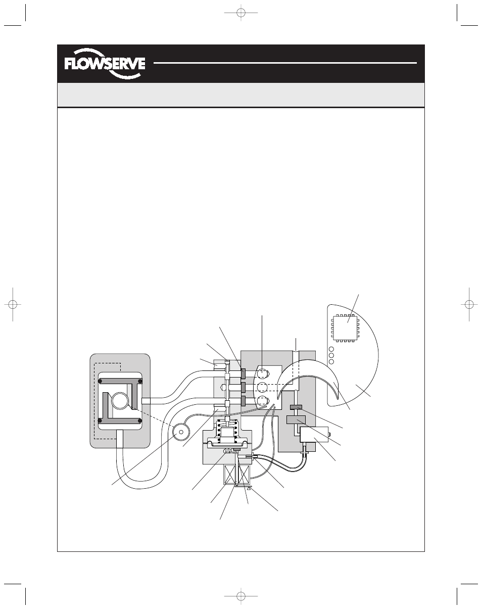
Air-to-Open
Configuration
Figure 1: Logix 1000 Digital Positioner Schematic
Spool Valve
Flame Arrestors
LED
Display
Collector Board
Pressure Sensor
Digital Position
Algorithm
Steam Position
Sensor
Exhaust
Hall Effect Sensor
Electromagnetic Coil
Nozzle
Flame
Arrestor
Flapper
Orifice
Regulator
Flame Arrestor
Ribbon Cable
Main PCB Tray
OUTOUT 1
OUTOUT 2
Exhaust
Filter
Air Supply
FCD AXAIM0064-00 (AUTO-64) 08/04
Page: 2 of 16
© 2004, Flowserve Corporation, Printed in U.S.A.
(AXAIM0096-00) Logix 1000 IOM 8/6/04 3:34 PM Page 2