Flowserve 1000 Series Digitial Positioner User Manual
Page 12
FCD AXAIM0064-00 (AUTO-64) 08/04
Page: 12 of 16
© 2004, Flowserve Corporation, Printed in U.S.A.
Logix Series 1000 Digital Positioner
Installation, Operation and Maintenance Instructions
Flowserve Corporation
1350 N. Mountain Springs Parkway
1978 Foreman Dr.
Flow Control Division
Springville, Utah 84663-3004
Cookville, TN 38501
www.flowserve.com
Phone: 801 489 2233
Phone: 931 432 4021
© TriCom, Inc., 2004, All Rights Reserved.
open or air-to-close (this is determined by the mechanical
tubing of the actuator). The LIN_VALV/ROT_VALV button
allows the user to select linear or rotary feedback linkage.
The LIN/CUSTOM option allows selection of linear or custom
control characterization. If Custom is selected, the positioner
activates custom characterization. If the device is being
installed for the first time, the default custom
characterization is equal percent. However, if a custom curve
has been previously loaded, the previous curve will be used.
The DIP switch settings are only read after the Quick-Cal
button is pressed; otherwise, the settings do not have any
effect on positioner operation. The DIP switch settings will
override any previous configuration done using ValTalk or
the HART hand-held. Press the Quick-Cal button for five
seconds. If the button is released before five seconds have
elapsed, no action will be taken. After five seconds, the
positioner will begin a stroke calibration. Release the Quick-
Cal button once calibration has started. The positioner will
automatically stroke the valve. No LED will blink during this
process. If the calibration was successful, upon completion
the green LED will blink and the valve will be in control
mode. If the yellow LED blinks immediately after a stroke
calibration, this usually indicates that the valve did not
stroke. Check the air supply and cable connections. If a
calibration error occurred, the red LED will blink. The cause
of a red LED is generally a stem position linkage/feedback
sensor alignment problem. For linear linkage, the active
electrical feedback angle is 65 degrees. For rotary linkage,
the active electrical feedback angle is 95 degrees. The red
LED indicates that the mechanical travel is not centered
within the electrical sensor travel. If a red LED is blinking
after a stroke calibration, loosen the feedback sensor
mounting screws as shown in Figure 15. Turn the stem
position sensor slowly while watching the LED indicators.
Try small movements, both clockwise and counter-
clockwise. If the yellow LED begins to blink, the feedback
sensor has been correctly moved into range. Tighten the
feedback sensor mounting screws and repeat the Quick-Cal
procedure. If the LED remains red even after moving the full
length of the sensor slot, verify the following items:
LIN_VALV/ROT_VALV DIP switch setting, stem clamp and
take-off arm height.
NOTE: If the stroke stops in the closed position, the error
occurred when the position sensor/linkage was at closed
position. If the stroke stops in the open position, the error
occurred when position sensor/linkage was at the open
position. No calibration parameters are saved if an error
occurs. If the power to the positioner is removed, the unit
will power-up with the previous configuration parameters.
A successful calibration will save parameters.
If the valve does not stroke after pressing the Quick-Cal
button, this may be an indication that the internal regulator
pressure and/or the driver module minimum pressure is low.
Refer to the following instructions to check and set the
internal regulator and minimum pressure settings.
Note that the tools and equipment used in the next two
procedures are from indicated vendors.
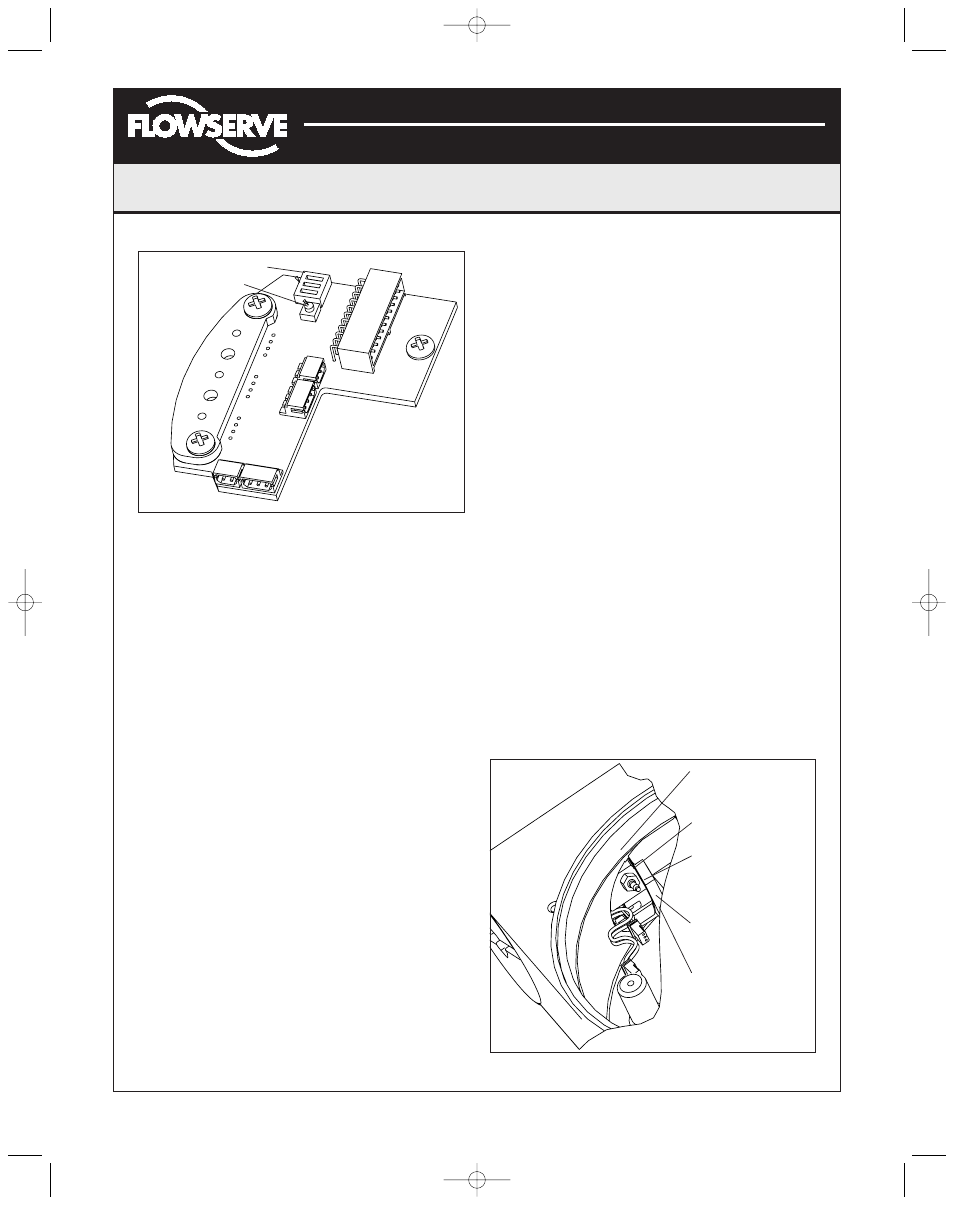
Figure 16: Quick-Cal Button
Figure 17: Driver Module
Quick-Cal DIP Switch
Quick-Cal Button
Minimum Pressure
Test Port
No.10-32 x .06 Barb
No.10-32 x Swivel
ELL Pneumadyne
Part No. SFL-10
No.10-32 x .016
Orifice
Pressure from
Internal Regulator
Output to be tubed
to this orifice
(AXAIM0096-00) Logix 1000 IOM 8/6/04 3:34 PM Page 12