Flowserve DDC-100 Modbus Direct-to-Host User Manual
Page 10
14
DDC-100 Direct-to-Host Programming Guide
FCD LMAIM4019-00
FCD LMAIM4019-00
DDC-100 Direct-to-Host Programming Guide
15
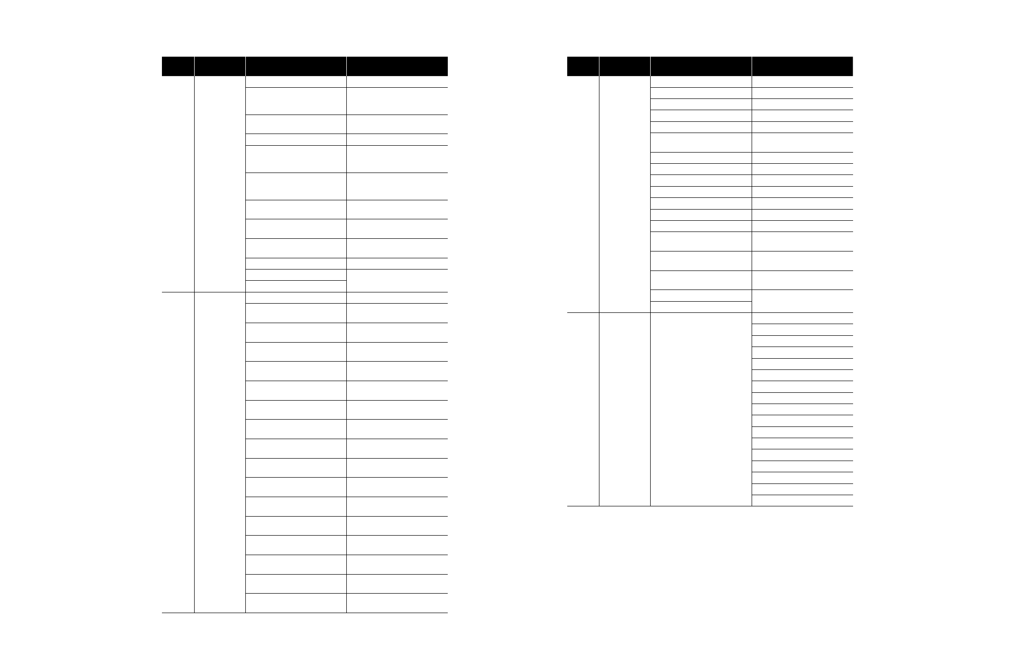
Table 3.5 – Field Unit Register Definitions (continued)
Register
Number
Register Name
MX/DDC Meaning
UEC-3-DDC Meaning
11
Digital Outputs
Value of 16 Digital Outputs
Value of 16 Digital Outputs
Bit 0 Close contactor (interlocked)
Bit 0 Close contactor (interlocked),
I/O Module as MOV (Motor-
Operated Valve)
Bit 1 Open contactor (interlocked)
Bit 1 Open contactor (interlocked),
I/O Module as MOV
Bit 2 AS-1
Bit 2 Lockout or User Relay 3
Bit 3 AS-2
Bit 3 UEC-3-DDC Local push-
button switch LED, Relay 4
Clamshell and I/O Module
Bit 4 AS-3
Bit 4 UEC-3-DDC Local push-
button switch LED, Relay 5
Clamshell and I/O Module
Bit 5 AS-4
Bit 5 Relay 6 Clamshell and I/O
Module
Bit 6 AR-1 (Opt)
Bit 6 Relay 2 (K2), I/O Module
(non-interlocked)
Bit 7 AR-2 (Opt)
Bit 7 Relay 1 (K1), I/O Module
(non-interlocked)
Bit 8 AR-3 (Opt)
Bits 8-15 Field Unit Software vs. ID
Bit 9 Network Relay
Bits 10-15 Not Used
12
Digital Inputs 1
Value of 16 Digital Inputs
Value of 16 Digital Inputs
Bit 0 Remote Switch
Bit 0 Remote Switch, I/O Module
Input 8
Bit 1 Thermal Overload
Bit 1 Thermal Overload, I/O
Module Input 9
Bit 2 Open Torque Switch
Bit 2 Open Torque Switch, I/O
Module Input 10
Bit 3 Open Limit Switch
Bit 3 Open Limit Switch, I/O
Module Input 11
Bit 4 Close Torque Switch
Bit 4 Close Torque Switch, I/O
Module Input 12
Bit 5 Close Limit Switch
Bit 5 Close Limit Switch, I/O
Module Input 13
Bit 6 Not Used
Bit 6 Aux. Open Input, I/O Module
Input 14
Bit 7 Not Used
Bit 7 Aux. Close Input, I/O Module
Input 15
Bit 8 User Input 0, terminal 21
Bit 8 User Input 0, I/O Module
Input 0
Bit 9 User Input 1, terminal 10
Bit 9 User Input 1, I/O Module
Input 1
Bit 10 User Input 2, terminal 9
Bit 10 User Input 2, I/O Module
Input 2
Bit 11 User Input 3, terminal 6
Bit 11 User Input 3, I/O Module
Input 3
Bit 12 User Input 4, terminal 7
Bit 12 User Input 4, I/O Module
Input 4
Bit 13 User Input 5, terminal 5
Bit 13 User Input 5, I/O Module
Input 5
Bit 14 Opt User Input 6,
terminal 23
Bit 14 Input 6, I/O Module Input 6
Bit 15 Opt User Input 7,
terminal 24
Bit 15 Input 7, I/O Module Input 7
Table 3.5 – Field Unit Register Definitions (continued)
Register
Number
Register Name
MX/DDC Meaning
UEC-3-DDC Meaning
13
Digital Inputs 2
Value of 16 Digital Inputs
Value of 16 Digital Inputs
Bit 0 Not Used
Bit 0 Analog Input 1 lost
Bit 1 Not Used
Bit 1 Analog Input 2 lost
Bit 2 Analog input 1 lost
Bit 2 Analog Input 3 lost
Bit 3 Analog input 2 lost
Bit 3 Analog Input 4 lost
Bit 4 Network Channels A/B
timed out
Bit 4 Network Channels A/B
timed out
Bit 5 Not Used
Bit 5 Reserved
Bit 6 DDC board present
Bit 6 Reserved
Bit 7 I/O option board present
Bit 7 Reserved
Bit 8 Not Used
Bit 8 Reserved
Bit 9 Not Used
Bit 9 Reserved
Bit 10 Not Used
Bit 10 Reserved
Bit 11 Not Used
Bit 11 Reserved
Bit 12 Phase lost
Bit 12 Phase lost input, I/O Module
Input 18
Bit 13 Phase reverse
Bit 13 Phase reverse input, I/O
Module Input 19
Bit 14 Opt User Input 8,
terminal 25
Bit 14 Input 8, I/O Module Input 16
Bit 15 Not Used
Bit 15 Input 9, I/O Module Input 17
14
Timers and
Analog Channels
Bits 0-15 – Not Used
Value of 16 Bits
Bit 0 Analog Channel 1 Low
Bit 1 Analog Channel 2 Low
Bit 2 Analog Channel 3 Low
Bit 3 Analog Channel 4 Low
Bit 4 Analog Channel 1 High
Bit 5 Analog Channel 2 High
Bit 6 Analog Channel 3 High
Bit 7 Analog Channel 4 High
Bit 8 Open reversal time-out
Bit 9 Close reversal time-out
Bit 10 Jammed valve time-out
Bit 11 Network Channel A time-out
Bit 12 Network Channel B time-out
Bit 13 User 1 time-out
Bit 14 User 2 time-out
Bit 15 User 3 time-out