3 single-line multi-drop, 3 network polling, Host – Flowserve DDC-100 Modbus Direct-to-Host User Manual
Page 19
32
DDC-100 Direct-to-Host Programming Guide
FCD LMAIM4019-00
FCD LMAIM4019-00
DDC-100 Direct-to-Host Programming Guide
33
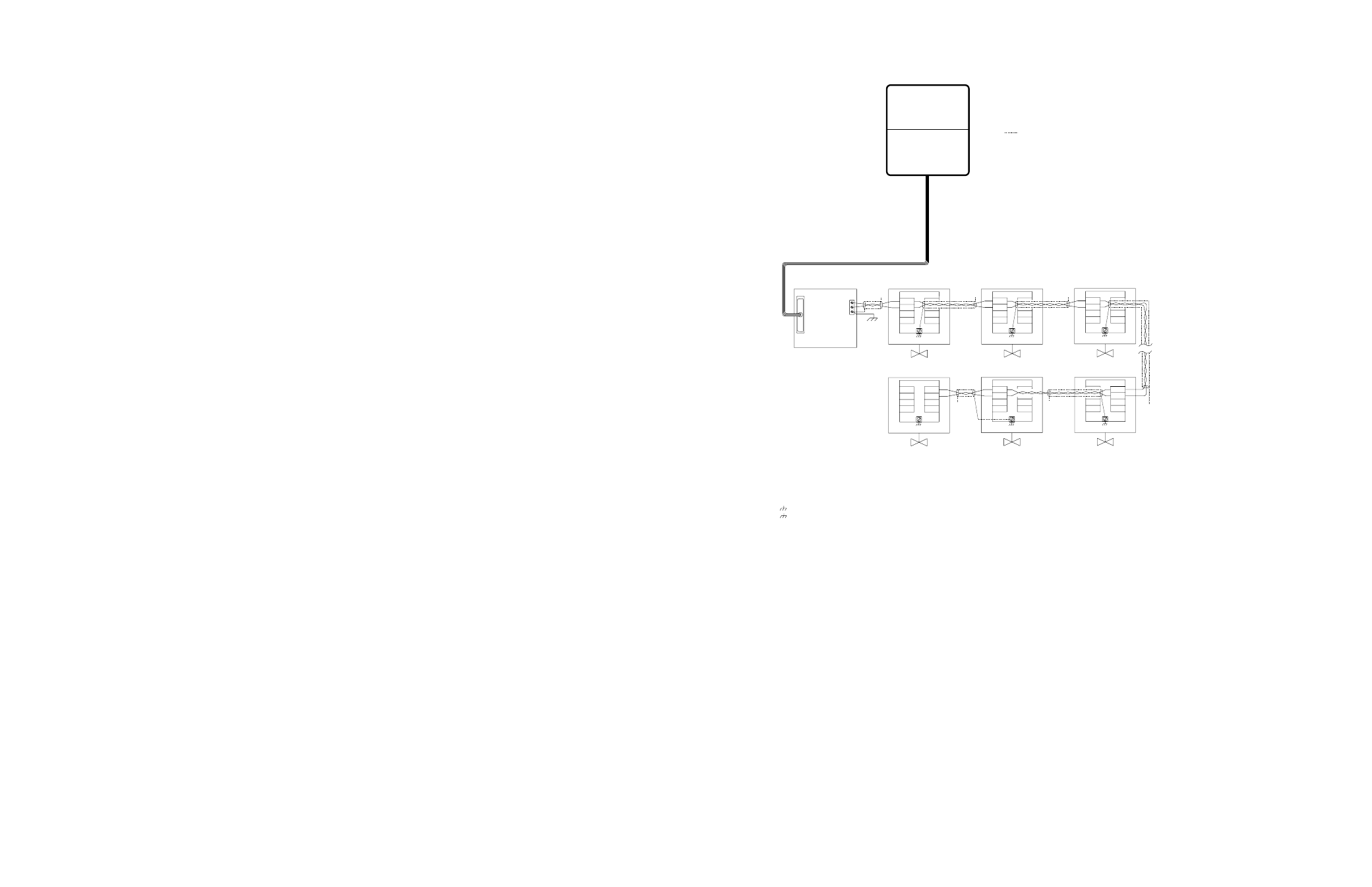
4.2.3 Single-Line Multi-drop
The single-line multi-drop topology is shown in Figure 4.3. Single-line multi-drop is wired by
cabling from the Host and connecting to the first field unit port A1. The cable to the next field unit
is attached to the same terminals on the first field unit and then run to port A1 on the second field
unit. This continues until the last field unit is connected.
A single-line multi-drop topology can simplify installation (especially when pre-existing wiring
is used), but it does not offer the extra reliability of a looped communication path. A line break
prevents communication with field units beyond the break, and a line short will cause a loss of
communication with all field units.
The maximum number of field units that can be accommodated by the single-line multi-drop
network is 28 units and the maximum distance between the Host and the last field unit is 1800
feet (550 m) without the use of repeaters. Note that all Limitorque field units can be wired to act as
repeaters by using ports A1 and A2.
Flowserve recommends use of the single-ended loop topology in lieu of single-line, multi-drop for
the MX-DDC.
NOTE: The single-line multi-drop topology requires the removal of termination resistors and bias
voltage jumpers from all but the last field unit. See the appropriate field unit manual or contact
Flowserve for assistance.
Figure 4.3 – DDC-100 Single-Line Multi-Drop Network
RS-232
RS-485
Diagnostic Note:
Earth Ground Note:
MOV-2
A1
A1*
A1
A1*
TB5
MOV-26
N/C
A1
A1*
A1
A1*
TB5
MOV-28
D-M
D-M*
D-S
D-S*
A1
A1*
TB4
TB3
TB5
Notes:
Legend
MOV
D-M
D-M*
D-S
D-S*
N/C
Data terminal is positive with respect to data* terminal
RS-232 to RS-485
converter with
surge suppression
Data 1
Earth Ground
(See Note 4)
See Note 5
See Note 5
See Note 5
1) Belden 3074F, 3105A, or 9841 shielded cable is recommended.
2) Correct polarity for field unit and network controller
connection is necessary for proper operation.
3) Connections shown are typical. The number of
MOVs shown may not indicate true system size.
4)
Earth ground: ground rod
5)
Earth ground: ground rod or lug in
actuator if actuator is grounded.
Polarity and level of the network’s data connection can
be checked by measuring voltage between data and
data* terminals. This voltage should be greater than
+200 mVDC with network controller network ports
disconnected.
If low impedance earth ground is not available at
each actuator, contact engineering for alternative
earth ground surge protection strategies.
Host
RS-232
PORT 1
Network Port A
N/C
N/C
N/C
D-M
D-M*
TB3
TB4
D-M
D-M*
TB4
TB3
Ground 3
Data* 2
- Motor-Operated Valve
- Data A1 (UEC-3-DDC)
- Data A1*(UEC-3-DDC)
- Data A2* (UEC-3-DDC)
- Shield
- No Connection
- Data A2 (UEC-3-DDC)
MOV-1
A1
A1*
A1
A1*
TB5
See Note 5
D-M
D-M*
TB3
TB4
MOV-3
A1
A1*
A1
A1*
TB5
See Note 5
D-M
D-M*
TB3
TB4
MOV-27
A1
A1*
A1
A1*
TB5
See Note 5
D-M
D-M*
TB3
TB4
N/C
N/C
4.3 Network Polling
Network polling is a Host-generated systematic request for information from each field unit on
the serial communication network. This systematic process updates the Host Data Table (Poll
Table) with each complete network scan. By utilizing this sequential update sequence, the Host can
operate more efficiently because the Data Table always contains up-to-date information.
In systems in which there is no up-to-date Data Table, the Host must check the status of a field unit
every time it needs to actuate a valve. This check is required to determine if the actuator is capable
of movement prior to the issuance of the command to move. The continuous poll process should
be enabled at all times to allow peak network performance.
Safeguards are built into the Limitorque field units that operate in the event of a disruption in the
polling process. The field unit network watchdog timer will start a field unit reset process if the field
unit does not recognize that it has been polled in a specified time interval (default 60 seconds). This
field unit reset process is designed to clear any errors in the field unit that may prevent successful
communication to a Host device.