8 modbus function code 15 (force multiple coils) – Flowserve DDC-100 Modbus Direct-to-Host User Manual
Page 15
24
DDC-100 Direct-to-Host Programming Guide
FCD LMAIM4019-00
FCD LMAIM4019-00
DDC-100 Direct-to-Host Programming Guide
25
3.2.8 Modbus Function Code 15 (Force Multiple Coils)
This function code allows the user to force multiple coils with a single command and uses the same
coil assignments as the function code 05.
It should be noted that the coils are operated from the lowest coil number to the highest. Forcing
coil 1 or 2 OFF (0) is considered a stop command, sending a 15 command to force two coils
starting with coil 1, with coil 1 ON and coil 2 OFF, would result in the unit stopping, since coil 2 is
forced OFF after coil 1 is forced ON.
To prevent inadvertent Stop commands from being issued, it is recommended to force one coil at a
time.
Available digital outputs for DDC-100 Field Units are listed in Table 3.6. Force multiple coil
commands should be issued only once for the desired field unit control. Repeated issuance of an
acknowledged command will degrade network performance.
NOTE: This function code is implemented in UEC-3-DDC Modbus Firmware 2.00 and greater and
MX-DDC Firmware 02/01.00 and greater
Example of force coil command
Force coil 1 of field unit 1 ON. This will CLOSE the valve controlled by field unit 1.
Query: 010F000000010101EF57
Response: 010F00000001940B
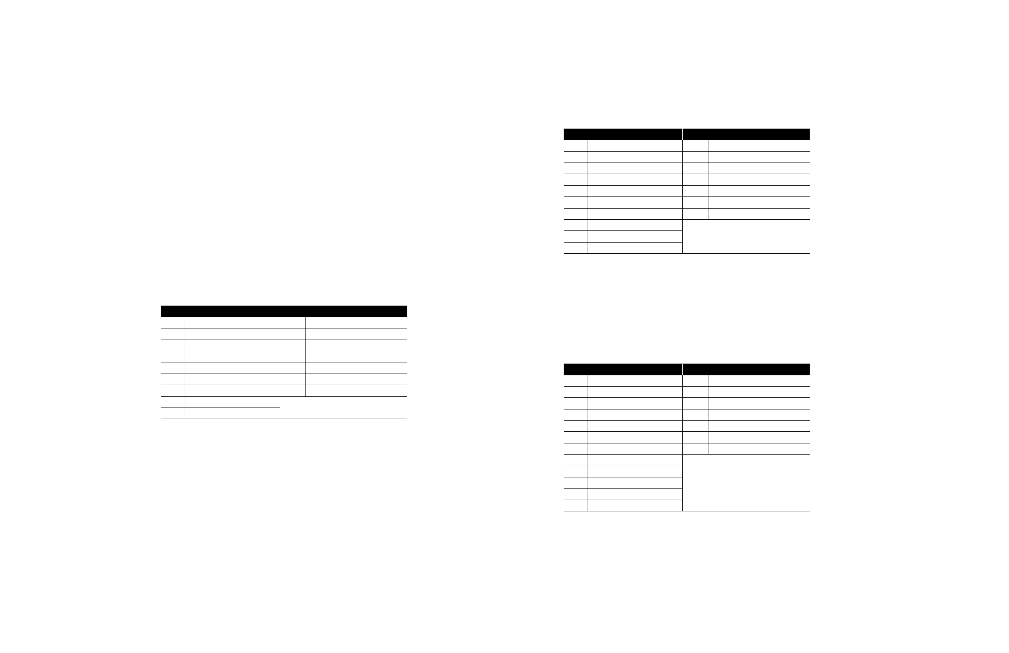
Message Breakdown
Query
Response
01
Slave Address
01
Slave Address
0F
Function
0F
Function
00
Coil Address Hi
00
Coil Address Hi
00
Coil Address Lo
00
Coil Address Lo
00
Quantity of Coils Hi
00
Quantity of Coils Hi
01
Quantity of Coils Lo
01
Quantity of Coils Lo
01
Byte Count
940B
Error Check (LRC or CRC)
01
Force Data Lo
EF57
Error Check (LRC or CRC)
Note: 000000010101h equals Coil Address 00000001 (field unit coil 1)
000100010101h equals Coil Address 00000010 (field unit coil 2)
3.2.9 Modbus Function Code 16 (Preset Multiple Registers)
This function code is used to preset single or multiple registers in the field unit and uses the same
predetermined register values as the function code 06. This function code is typically used to
command the DDC-100 Field Unit by writing values to the 40001 and/or 40002 registers.
Modbus function code 16 command values for controlling the DDC-100 Field Unit are given in Table
3.7. Each command should be issued only one time for the desired field unit control. Repeated
issuance of an acknowledged command will degrade network performance.
The normal response returns the slave address, function code, starting address, and quantity of
registers preset.
NOTE: This function code is implemented in UEC-3-DDC Modbus Firmware 2.00 and greater and
MX-DDC Firmware 02/01.00 and greater.
Example of Field Unit Command
Write the command to open an actuator (actuator open) to field unit number 1. This corresponds to
writing the value 256 into field unit register 40001.
Query: 011000000001020100A7C0
Response: 01100000000101C9
Message Breakdown
Query
Response
01
Slave Address
01
Slave Address
10
Function
10
Function
00
Starting Address Hi
00
Starting Address Hi
00
Starting Address Lo
00
Starting Address Lo
00
Number of Registers Hi
00
Number of Registers Hi
01
Number of Registers Lo
01
Number of Registers Lo
02
Byte Count
01C9
Error Check (LRC or CRC)
01
Preset Data Hi
00
Preset Data Lo
A7C0
Error Check (LRC or CRC)
Example of “Move-To” Command
Move an actuator at address 1 to 50% of open by presetting registers 40001 with the value 6656,
and register 40002 with the value 50 in a single write command. The actuator will receive this
message and move to a position of 50% open.
Query: 011000000002041A0000327562
Response: 01100000000241C8
Message Breakdown
Query
Response
01
Slave Address
01
Slave Address
10
Function
10
Function
00
Starting Address Hi
00
Starting Address Hi
00
Starting Address Lo
00
Starting Address Lo
00
No. of Registers Hi
00
No. of Registers Hi
02
No. of Registers Lo
02
No. of Registers Lo
04
Byte Count
41C8
Error Check (LRC or CRC)
1A
Preset Data Hi
00
Preset Data Lo
00
Preset Data Hi
32
Preset Data Lo
7562
Error Check (LRC or CRC)
Note: The single register write “Move-to” command may also be used with the function code
16. This function code may also utilize the Single Register write “move-to” command.