7 modbus function code 08 (diagnostics) – Flowserve DDC-100 Modbus Direct-to-Host User Manual
Page 14
22
DDC-100 Direct-to-Host Programming Guide
FCD LMAIM4019-00
FCD LMAIM4019-00
DDC-100 Direct-to-Host Programming Guide
23
Second Command
Query B30600001A009978
Response B30600001A009978
Second Command Message Breakdown
Query
Response
B3
Slave (Field Unit) Address
B3
Slave (Field Unit)
Address
06
Function
06
Function
00
Register Address Hi
00
Register Address Hi
00
1
Register Address Lo
00
Register Address Lo
1A
Force Data Hi
1A
Preset Data Hi
00
2
Force Data Lo
00
Preset Data Lo
9978
Error Check (CRC)
9978
Error Check (CRC)
Note 1: 0000h equals Register Address 40001 (field unit register 1, command register).
Note 2: 1A00h equals 6656.
Example of single register write “move-to” command
This command allows a Host to issue the “move-to” command with a single write utilizing the
Modbus function code 06. Register 1 will be used to complete this command.
Rules for utilizing this command:
• Field unit scaling must be configured for 0-100.
• To use the hexadecimal method of determining a single write “move-to” command, 0x4B is
always placed into the Hi Byte of Register 1.
• The desired position value is always placed into the Lo Byte of Register 1.
To move the actuator to a position of 50%, place the value 0x4B in the high byte and the value of
0x32 (50 decimal) into the low byte.
Example:
Hex format: 0x4B32
To use the decimal method of determining a single write “move-to” command, add the desired
position value to 19200.
Example:
Desired position: 50%
19200 + 50 = 19250
Example of single write “move-to” command
Move an actuator at address 1 to 50% of open by writing the value of 19250 (0x4B32) to the field
unit 40001 register. The actuator will then move to a position of 50% open.
Example
Query: 010600004B323EEF
Response: 010600004B323EEF
Message Breakdown
Query
Response
01
Slave Address
01
Slave Address
06
Function
06
Function
00
Starting Address Hi
00
Starting Address Hi
00
Starting Address Lo
00
Starting Address Lo
4B
Preset Data Hi
4B
Preset Data Hi
32
Preset Data Lo
32
Preset Data Lo
3EEF
Error Check (LRC or CRC)
3EEF
Error Check (LRC or CRC)
3.2.7 Modbus Function Code 08 (Diagnostics)
This function code provides a series of tests for checking the communication system between
the Host and field units (slaves), or for checking various error conditions within the field unit.
This function code uses a two-byte subfunction code field in the query to define the type of test
to be performed. The field unit echoes both the function code and subfunction code in a normal
response. It does not affect the field unit in any way. If this exchange is successful, then the
communication is successful.
A listing of the supported diagnostic two-byte subfunction codes is given in Table 3.8.
Example
Request a loopback (return query data) from the field unit at network address 3.
Query 030800000000E1E9
Response 030800000000E1E9
Message Breakdown
Query
Response
03
Slave (Field Unit) Address
03
Slave (Field Unit) Address
08
Function
08
Function
00
Subfunction Hi
00
Subfunction Hi
00
Subfunction Lo
00
Subfunction Lo
00
Data Hi
00
Data Hi
00
Data Lo
00
Data Lo
E1E9
Error Check (CRC)
E1E9
Error Check (CRC)
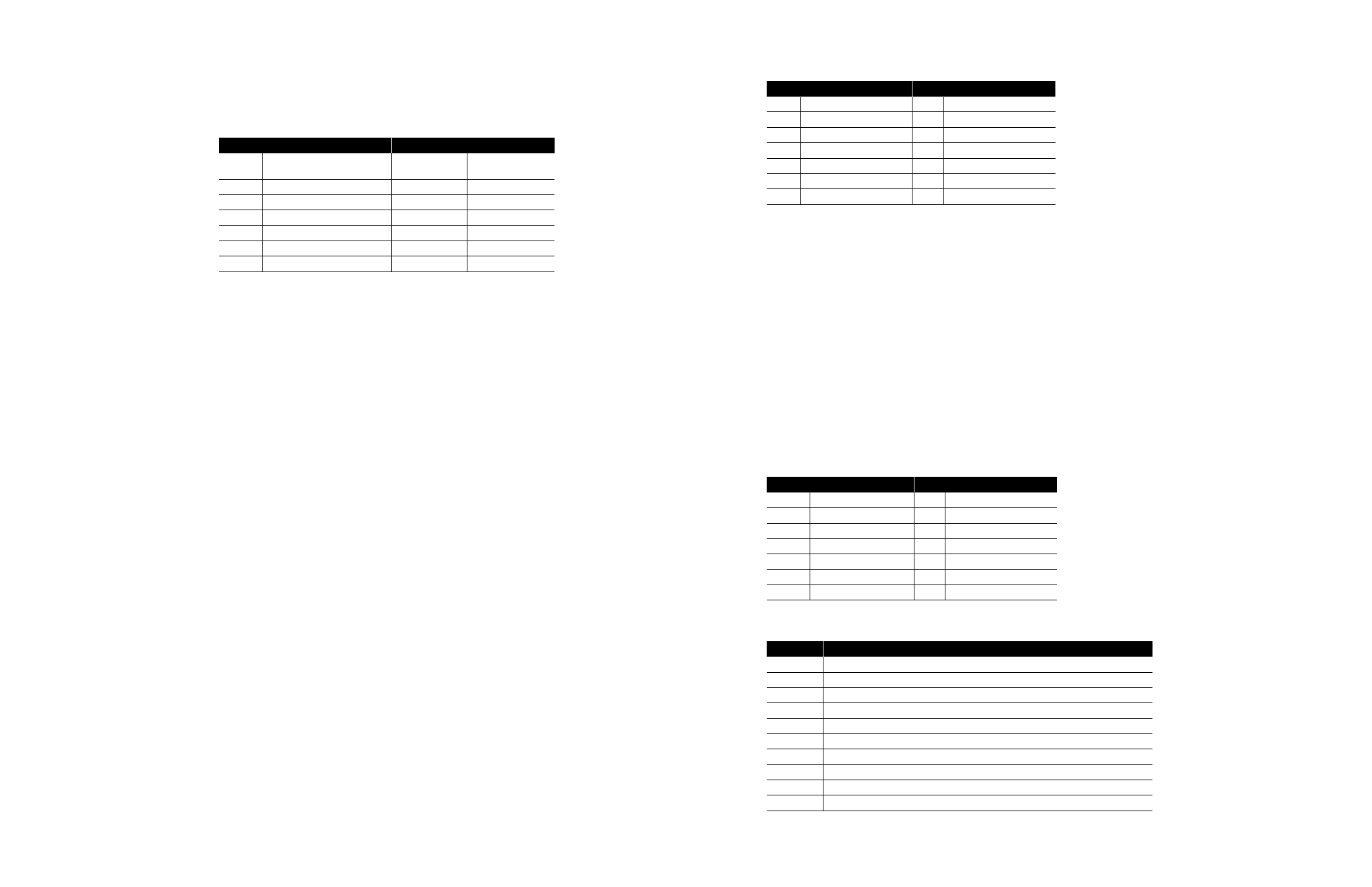
Table 3.8 – Diagnostic Codes Supported by the DDC-100 Field Unit
Code
Name
00
Return Query Data
01
Restart Communication Option
02
Return Diagnostic Register1
03
Change ASCII Input Delimiter
04
Force Listen-Only Mode
10 (0A Hex)
Clear Counters and Diagnostics Register
11 (0B Hex)
Return Bus Message Count
12 (0C Hex)
Return Bus Communication Error Count
13 (0D Hex)
Return Bus Exception Error Count
14 (0E Hex)
Return Slave Message Count
Note 1: Contains DDC-100 Field Unit diagnostic information. For engineering use only.