Flowserve DDC-100 Modbus Direct-to-Host User Manual
Page 26
46
DDC-100 Direct-to-Host Programming Guide
FCD LMAIM4019-00
FCD LMAIM4019-00
DDC-100 Direct-to-Host Programming Guide
47
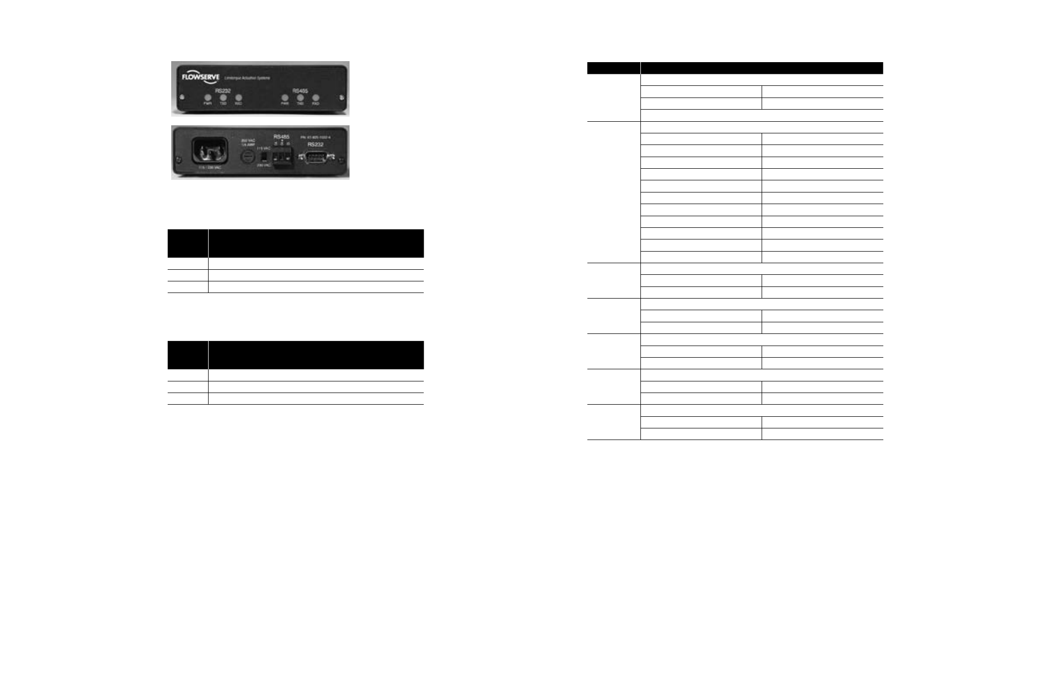
Figure 5.4 – Front and Back Panels of Self-Steering Converter
Table 5.8 – RS-232/RS-485 Converter (P/N 61-825-1032-4) RS-232 Connector
RS-232
Connector
Pin Number
Function
2
Transmit data (TxD)1
3
Receive data (RxD)1
5
Signal ground
Note 1: The pin numbers of these signals can be reversed with jumpers inside the converter
box (see Table 5.10).
Table 5.9 – RS-232/RS-485 Converter (P/N 61-825-1032-4) RS-485 Connector
RS-485
Connector
Pin Number
Function
1
Data
2
Data*1
3
Earth ground2
Note 1: Indicates negative side of signal.
Note 2: Must be connected to earth ground to assure surge protection.
c
WARNING: Disconnect the converter from the power source and from the Host and
network before removing the cover. Potentially lethal voltages are present inside the
enclosure when it is connected to the power source.
Table 5.10 – RS-232/RS-485 Converter (P/N 61-825-1032-4) Jumpers
1
Jumper
Function
JP1 and JP2
Bias and termination for RS-485 data lines
Position 1:2
Adds bias and termination
Position 2:3
Disables bias and termination
Both jumpers must be in the same position
JP3
BAUD Rate Select
Position 0
Not Used
Position 1
62.5K
Position 2
38.4K
Position 3
19.2K
Position 4
9600
Position 5
4800
Position 6
2400
Position 7
1200
Position 8
600
Position 9
N/A
Position 10
N/A
JP4
Protocol Select
Position 1:2
BITBUS
Position 2:3
Modbus
JP5
Reverses RS-232 TxD and RxD lines
DCE 1:2, 3:4
DTE 1:3, 2:4
JP6
XTAL Select.
Position 1:2
62.5 Baud
Position 2:3
Standard Baud
JP7
Asynchronous or HDLC
2
Position 1:2
HDLC
Position 2:3
Asynchronous
JP8
Filter Ground
Position 1:2
Common Ground
Position 2:3
Isolated Ground
Note 1: The jumpers JP1 through JP8 are located inside the converter. The enclosure must be opened for
access. The positions for the jumpers are shown in the silk screen on the PC board.
Note 2: High-Level Data Line Control