Figure 5.2 – rs-232/rs-485 cable diagram, Table 5.1 – rs-232/rs-485 converter specifications – Flowserve DDC-100 Modbus Direct-to-Host User Manual
Page 24
42
DDC-100 Direct-to-Host Programming Guide
FCD LMAIM4019-00
FCD LMAIM4019-00
DDC-100 Direct-to-Host Programming Guide
43
Table 5.1 – RS-232/RS-485 Converter Specifications
Parameter
Specification
Baud Rate
600 baud to 62.5 kb
Protocols
Modbus, BITBUS
Connectors
RS-232 - DB9 Male
RS-485 - Detachable five-contact (Steered Converter P/N 61-825-0966-4)
RS-485 - Detachable three-contact (Self-Steered Converter
P/N 61-825-1032-4)
Indicators
PWR1, PWR2, TxD, RxD, RTS/DTR (Steered Converter P/N 61-825-0966-4)
RS-232 - Power, TxD, RxD
RS-485 - Power, TxD, RxD
(Self-Steered Converter P/N 61-825-1032-4)
Surge Protection
In accordance with IEC-801.5 to 1.5 kV
Power
110 - 220 VAC 50/60 Hz, single-phase
10 W, Switch Selectable
Fuse
250 VAC, .25 A
Operating Temperature Range 0 to 70°C (32 to 158°F)
Operating Humidity
95% Relative (Non-condensing)
The ordering information for the two converter types is given in Tables 5.2 and 5.3.
Table 5.2 – Steered Converter Assembly (P/N 22300-7591)
Description
Part Number
Quantity
Complete converter w/AC power cord
61-825-0966-4
2
Cable, RS-232, DB25M to DB9F, 6 feet long ESC-AT-PS/2Cable
2
Three-unit bracket for 19" rack mounting
ES5-K1PT-H03B
1
Blank insert panel for three-unit rack
ES5-19216-001B
1
Note 1: Individual assembly components may be purchased from Flowserve.
Table 5.3 – Self-Steering Converter Assembly (P/N 22300-7601)
Description
Part Number
Quantity
Complete converter w/AC power cord
61-825-1032-4
2
Cable, RS-232, DB25M to DB9F, 6 feet long ESC-AT-PS/2Cable
2
Three-unit bracket for 19" rack mounting
ES5-K1PT-H03B
1
Blank insert panel for three-unit rack
ES5-19216-001B
1
Note 1: Individual assembly components may be purchased from Flowserve.
Converter assemblies 22300-759 and 22300-760 include two DB25M to DB9F modem cables.
These cables are appropriate for most Host connections. To determine if these cables are compat-
ible with your Host RS-232 communication port(s), contact your System Integrator.
The System Integrator will review wiring requirements for the Host RS-232 port(s) with the
converter-assembly cables. Should the cables not be compatible with the Host RS-232 port, the
cables may be altered, a modifying connector installed, or new cables may be purchased at a local
cable supplier.
Individual converter part numbers 61-825-0966-4 and 61-825-1032-4 do not include a serial cable
for connection to a Host. It is the responsibility of the System Integrator to obtain the correct serial
cable based on the Host RS-232 port connector and Limitorque converter RS-232 port connector.
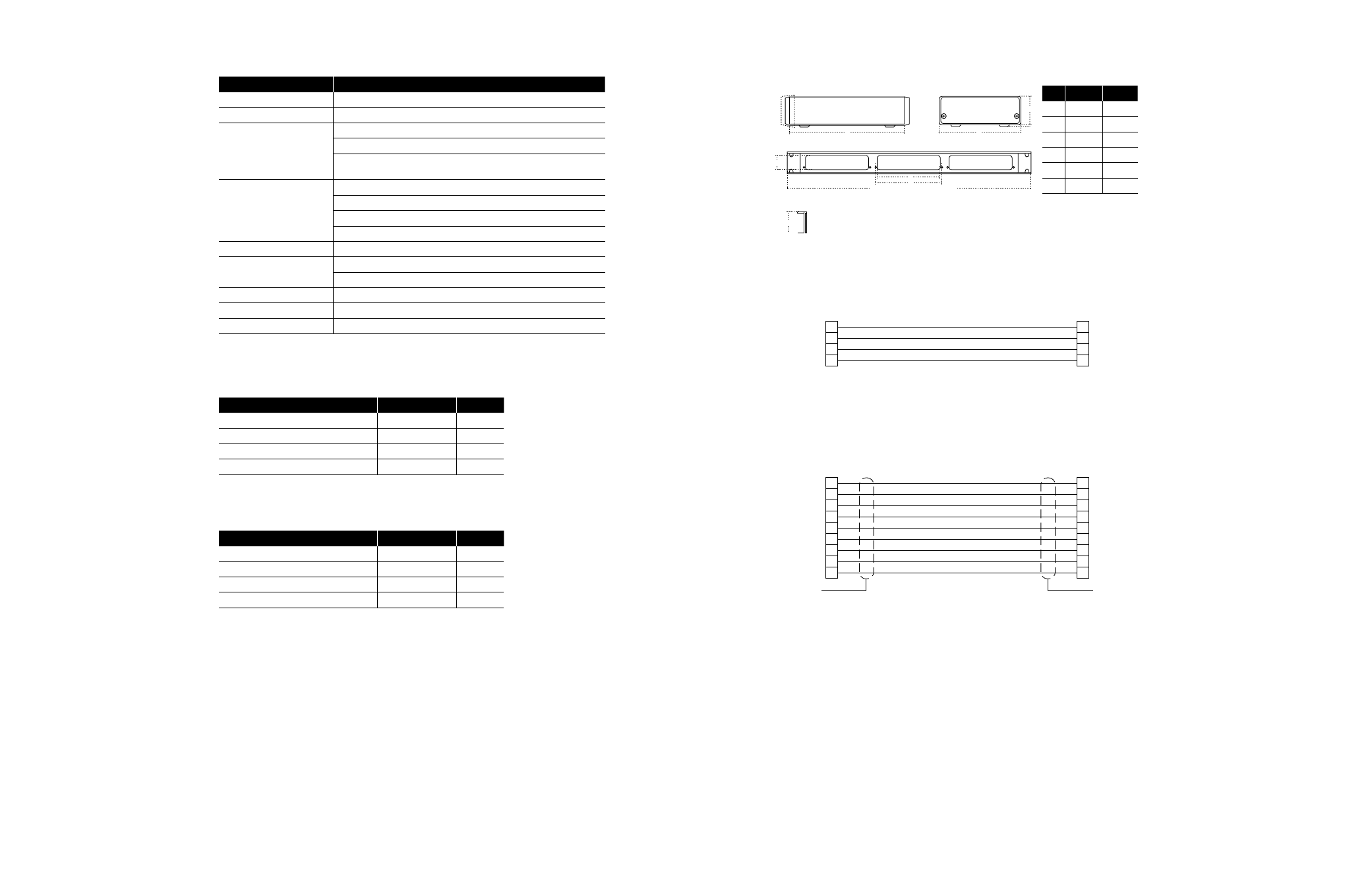
Figure 5.1 – RS-232/RS-485 Converter Dimensions and Rack Mount Kit
C
End View
A
B
D
Front View
1.12
18.95 (For standard 19" rack)
V
F
Rack Mounting Kits
End View
1.72
inches
mm
A
5.6
141.5
B
1.5
38.6
C
6.0
152.4
D
0.2
5.3
F
5.2
130.9
V
5.0
128
Figure 5.2 – RS-232/RS-485 Cable Diagram
25-Socket Female
Connector to A/B Serial
Expander Comm 2&3
2
3
7
4
Transmit Ou t
Receive In
Signal GND
RTS Out
(Used for
steering)
Transmit In
Receive Ou t
Signal GND
RTS In
25-Socket Female
Connector to RS-232/485
Converter
2
3
7
4
Limitorque P/N ESC-BC 00801
For use with RS-232/RS-485 Converter
P/N 61-825-0900-3 only .
25-Pin
Male
3
2
7
8
6
5
1
4
9
9-Pin
Female
2
3
4
5
6
7
8
20
22
Limitorque P/N ESC-AT-PS/2Cable
for use with RS-232/RS-485 Converters
P/N 61-825-0966-4 and P/N 61-825-1032-4
Shell
Shield
Shell
Shield
5.1.1 RS-232/RS-485 Control Line Steered Converter
(P/N 61-825-0966-4)
This is the standard converter offered by Flowserve for use with Limitorque networks. This
converter provides isolation, surge protection, data rate, and distance capability that is equivalent
to the self-steered converter. This converter uses either Host RS-232 port RTS (Request To Send)
or DTR (Data Terminal Ready) (DIP switch selectable) signals to steer the RS-485 data direction.
This converter also provides a directional steering output for Limitorque’s A/B Switch (P/N EEC-
90001840).
In the converter, the RS-232 data is converted to TTL signals. The signals drive indicating LEDs and
inputs of optical couplers that drive the RS-485 converter circuit. The optical couplers isolate the
Host hardware from the RS-485 Network. The RS-485 circuit is bi-directional and must be steered