Table 3.4 – status bit definitions, Table 3.4 – status bit definitions (continued), 2 modbus function code 02 (read input status) – Flowserve DDC-100 Modbus Direct-to-Host User Manual
Page 7
8
DDC-100 Direct-to-Host Programming Guide
FCD LMAIM4019-00
FCD LMAIM4019-00
DDC-100 Direct-to-Host Programming Guide
9
Table 3.3 – DDC-100 Coil Assignments, Modbus Function Code 01 Usage for Digital Outputs
Coil
Number
Bit
Number MX/DDC
UEC-3-DDC
DDC-100 Clamshell
I/O Module
1
00
Close / Stop
Close / Stop
Close / Stop
Do Not Use
2
01
Open / Stop
Open / Stop
Close / Stop
Do Not Use
3
02
AS-1
Lockout or Relay #3
Lockout or Relay #3
Relay #3
4
03
AS-2
Do Not Use
Relay #4
Relay #4
5
04
AS-3
Do Not Use
Relay #5
Relay #5
6
05
AS-4
Relay #6
Relay #6
Relay #6
7
06
AR-1 (Opt)
Do Not Use
Do Not Use
Relay #21
8
07
AR-2 (Opt)
Do Not Use
Do Not Use
Relay #12
9
08
AR-3 (Opt)
Do Not Use
Do Not Use
Do Not Use
Note 1: Relay #2 is physical Relay K2.
Note 2: Relay #1 is physical Relay K1.
Example
Poll field unit number 3 for 8 coils starting at coil 1.
Query 0301000000083C2E
Response 03010118503A
Message Breakdown
Query
Response
03
Slave (Field Unit) Address
03
Slave (Field Unit)
Address
01
Function
01
Function
00
Starting Address Hi
01
Byte Count
00
Starting Address Lo
18 1
Data (Coils 8 - 1)
00
No. of Points Hi
503A
Error Check (CRC)
08
No. of Points Lo
3C2E
Error Check (CRC)
Note 1: 18h equals 00011000 or coils 4 and 5 are ON.
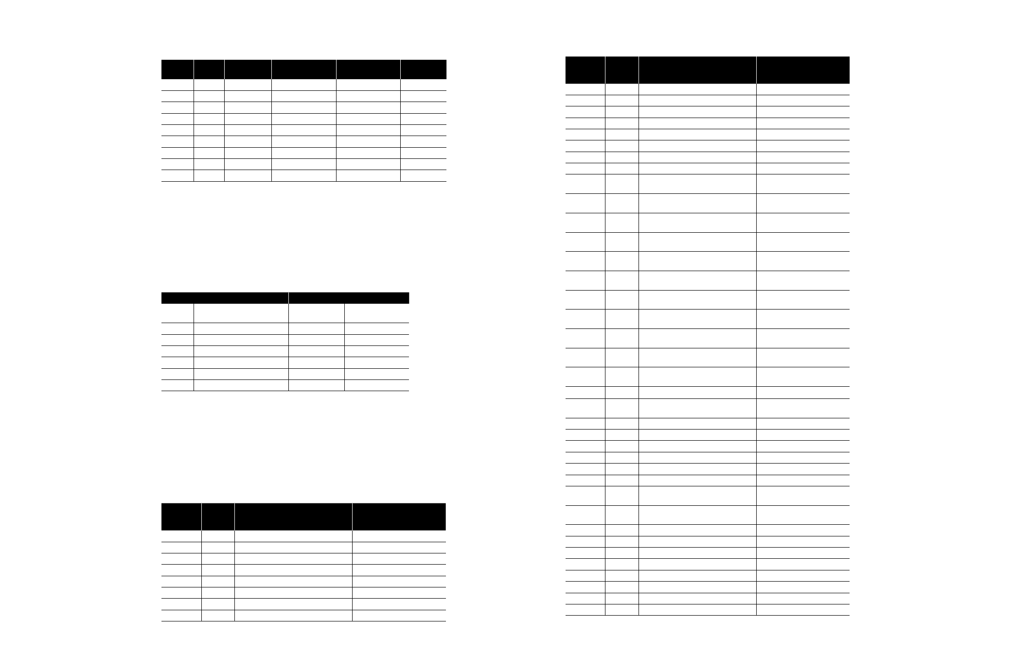
3.2.2 Modbus Function Code 02 (Read Input Status)
This function code is used to read the discrete input status bits in the DDC-100 Field Unit. The use
of this function code will provide the user with the input status bits that are used to develop holding
registers 9 through 13. The status bit inputs are contained in locations 10129-10208 for each
DDC-100 Field Unit and are defined in Table 3.4.
Table 3.4 – Status Bit Definitions
Bit Number
Modbus
Bit
Address
UEC-3-DDC and DDC-100 Clamshell
I/O Module
129
128
Opened
Not Used
130
129
Closed
Not Used
131
130
Stopped
Not Used
132
131
Opening
Not Used
133
132
Closing
Not Used
134
133
Valve jammed
Not Used
135
134
Actuator switched to local mode
Not Used
136
135
Combined fault
Not Used
Table 3.4 – Status Bit Definitions (continued)
Bit Number
Modbus
Bit
Address
UEC-3-DDC and DDC-100 Clamshell
I/O Module
137
136
Over-temperature fault
Not Used
138
137
Actuator failing to de-energize
Not Used
139
138
Channel A fault
Channel A fault
140
139
Channel B fault
Channel B fault
141
140
Open torque switch fault
Not Used
142
141
Close torque switch fault
Not Used
143
142
Valve operated manually fault
Not Used
144
143
Phase error
Not Used
145
144
Input “open verify” is not active after open
command is initiated
Not Used
146
145
Input “close verify” is not active after close
command is initiated
Not Used
147
146
Input “open verify” is active after open
command is de-energized
Not Used
148
147
Input “close verify” is active after close
command is de-energized
Not Used
149
148
“Ph_det” (Phase Detect) input is active.
One or more phases is missing
Not Used
150
149
“Ph_seq” (Phase Sequence) input is active.
Reverse phase sequence is occurring
Not Used
151
150
Valve manually moved from mid-travel to
open
Not Used
152
151
Valve manually moved from open to
mid-travel
Not Used
153
152
Valve manually moved from mid-travel to
close
154
153
Valve manually moved from close to
mid-travel
Not Used
155
154
Network emergency shutdown (ESD) is
active
Not Used
156
155
Local emergency shutdown is active
Not Used
157
156
Field unit microprocessor has reset since
the last poll
Not Used
158
157
Wrong rotation
Not Used
159
158
Opening in local mode
Not Used
160
159
Closing in local mode
Not Used
161
160
Close contactor (interlocked)
Not Used
162
161
Open contactor (interlocked)
Not Used
163
162
Lockout or user, Relay 3
Relay 3
164
163
Local pushbutton switch LED (UEC-3)
Relay 4 (Clamshell)
Relay 4
165
164
Local pushbutton switch LED (UEC-3)
Relay 5 (Clamshell)
Relay 5
166
165
User, Relay 6
Relay 6
167
166
Close contactor (non-interlocked)
Relay 2 (K2)
168
167
Open contactor (non-interlocked)
Relay 1 (K1)
169
168
Field unit software vs. ID
Field unit software vs. ID
170
169
Field unit software vs. ID
Field unit software vs. ID
171-176
170-175
Field unit software vs. ID
Field unit software vs. ID
177
176
Remote switch
User Input 8
178
177
Thermal overload
User Input 9